Table of Contents
Advertisement
Quick Links
Chapter 1
Chapter 1
Introduction
Introduction
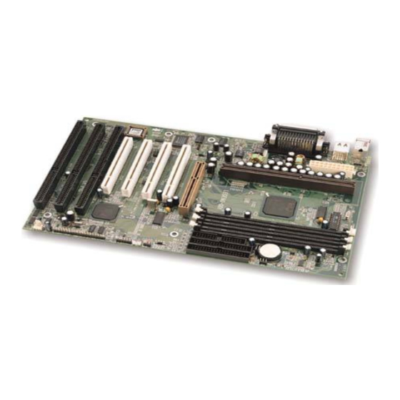
Overview
The BrillianX 8V green mother boar d utilizes the VIA BX chipset and provides a highly
integrated solution for fully compatibl e , high performance PC/ATX pl a tform. It provides 66MHz
and 100MHz system bus support for all Intel Pentium® II and Celeron
66MHz/100MHz SDRAM with SPD and 66MHz EDO DIMMs are supported. It also provides
advanced features suc h as AGP, wake-up on LAN and wake-up on internal/external mo-
dem . ManageEasy, our system management application is supplied to enable remote moni-
toring and configuration of the system.The green function is in compliance with the ACPI
specification. With the everlasting innovations of QDI such as SpeedEasy and LogoEasy
technologies, you get a powerful corporate system.
Key Features
Form factor
ATX form factor of 305mm x 190mm.
l
Microprocessor
Supports all Intel Pentium® II processors at 233/266/300/333MHz with 66MHz bus
l
speed and 350/400/450MHz with 100MHz bus speed.
Supports all Intel® Celeron
l
speed.
Supports 66MHz and 100MHz host bus speed.
l
CPU core frequency = Bus speed x2.5, x3, x3.5, x4, x4.5, x5, x5.5
l
CPU core supply voltage adjustable from 1.3V to 3.5V through on- board switching
l
voltage regulator with VID(Voltage ID).
Chipset
VIA BX c hipset: VT82C692BX AGP controller
l
VT82C596 PCI to ISA bridge.
System m em ory
Provides three 168 pin 3.3V unbuffered DIMM sockets.
l
Supports both 66MHz/100MHz SDRAMs with SPD and 66MHz EDO DIMMs.
l
Mini m um memory size is 8MB, maximum memory size is 768MB.
l
SDRAM 64 bit data interface with ECC support.
l
TM
processors at 266/300/333 MHz with 66MHz bus
M a nua l f or B r i l l i a nX 8V
Chapter 1
TM
processors. Both
Advertisement
Table of Contents

Related Manuals for QDI BrillianX 8V


Summary of Contents for QDI BrillianX 8V
- Page 1 Introduction Overview The BrillianX 8V green mother boar d utilizes the VIA BX chipset and provides a highly integrated solution for fully compatibl e , high performance PC/ATX pl a tform. It provides 66MHz and 100MHz system bus support for all Intel Pentium® II and Celeron processors.
- Page 2 Introduction On-board IDE Supports two PCI PIO and Bus Master IDE ports. Two fast IDE interfaces supporting four IDE devices including IDE hard disks and CD - ROM drives. Supports up to PCI mode 4 timing. Supports “Ul t ra DMA/33” Synchronous DMA mode transferring up to 33 Mbytes/sec. Integrated 16x32bit buffer for IDE PCI Burst Transfers.
- Page 3 Chapter 1 Green function Supports ACPI (Advanced Configuration and Power Interface) and ODPM (OS Directed Power Management). Supports three green modes: Doze, Standby and Suspend. Expansion slots 3 ISA slots and 4 PCI slots. 1 AGP Slot. M a nua l f or B r i l l i a nX 8V...
- Page 4 -- This page is intentionally left blank -- M a nua l f or B r i l l i a nX 8V...
-
Page 5: Installation Instructions
chapter 2 Chapter 2 Chapter 2 Installation Instructions Installation Instructions This section covers External Connectors, Jumper Settings and Memory Configuration. Re- fer to the mother board layout chart for locations of all the jumpers, external connectors, slots and I/O ports. Furthermore, this section lists all necessary connector pin assignments for your reference. -
Page 6: Atx Power Supply Connector & Power Switch (Power)
Installation Instruction ATX Power Supply Connector & Power Switch (POWER) Be sure to connect the power supply plug to this connector in its proper orientation. The power switch (POWER) should be connected to a momentary switch. When powering up your system, first turn on the mec hanical switch of the power supply (if one is provided), then push once the power button. - Page 7 chapter 2 Green LED Connector (GREEN_LED) The green LED has four status. When no AC power supply is present, the LED is off. When the system is in soft power-down status, the LED glows dimly. When the system is powered up, the LED is on. When the system enters suspend mode, the LED will flash. Hardware Green Connector (SLEEP) Push once the switch connected to this header and the system will enter suspend mode.
- Page 8 Installation Instruction Fan Connector (CPUFAN, CHSFAN) These two fans are controllable. They will be automatic ally turned off after the sys tem enters suspend mode. Y ou also can choose not to turn the CPUFAN off by setting “CPUFAN In Suspend” as on in the “POWER MANAGEMENT SETUP” section of the BIOS. CPUFAN CHSFAN Wake-Up On LAN (WOL)
- Page 9 You can either get this information from System Monitor of BIOS software (optional) or QDI ManageEasy software. Sound Connector (SBLINK) This connector is for the usage of PCI sound card.
- Page 10 Installation Instruction There is one jumper setting on the motherboard, clear CMOS jumper JCC. Pin 1 of the jumper is located on the side with a thick white line (Pin 1 ), referring to the motherboard silkscreen. Jumpers with three pins will be shown as to represent pin1&pin2 connected and represent pin2 &...
-
Page 11: Bios Description
1. Create a bootabl e system floppy diskette, by typing Format A:/s from the DOS prompt under DOS6.xx or Windows 9x environment. 2. Copy FLASH.EXE from the directory \Utili t y on the QDI Motherboard Utility CD onto your new bootable diskette. - Page 12 Award BIOS Description /n: programs BIOS without prompting. If this option is chosen: Be sure your new BIOS is compatible with your MB. If not, the system will be damaged. /g: Retrieves BIOS file from BIOS ROM. Examples: A:\FLASH.EXE BIOSfile.bin A:\FLASH.EXE BIOSfile.bin /cdpc/n A:\FLASH.EXE BIOSfile.bin /g Note: FLASH utility runs incorrectly at Window s DOS prom pt.
-
Page 13: Load Setup Defaults
Chapter 3 AWARD BIOS Description Entering Setup Power on the computer, when the following message bri e fly appears at the bottom of the screen duri n g the POST (Power On Self Test), press <Del> key or simultaneously press the <Ctrl>... - Page 14 Award BIOS Description Figure-2 Standard CMOS Setup Menu Hard Disk Primary Master/Primary Slave/Secondary Master/Secondary Slave These categori e s identi f y the HDD types of 2 IDE channels i n stalled in the computer system. There are three choices provided for the Enhanced IDE BIOS: None, Auto, and User. ‘None’ means no HDD is installed or set;...
- Page 15 Chapter 3 Halt On This category determines whether or not the computer will stop if an error is detected during powering up. No errors The system boot will not stop for any errors that may be detected. All errors Whenever the BIOS detects a non-fatal error, the system will stop and you will be prompted.
-
Page 16: Speedeasy Cpu Setup
Award BIOS Description SpeedEasy CPU Setup Figure-3 SpeedEasy CPU Setup The following indicates the options for each item and describes their meanings . Item Option Description CPU Model BIOS automatically detects the CPU model, therefore this item is shown only. It could be Penti u m(R)II or Intel (R) Cel e ron(TM), depending on the processor chosen. -
Page 17: Bios Features Setup
Chapter 3 BIOS Features Setup Figure-4 BIOS Features Setup Menu The following indicates the options for each item and describes their meaning. Item Option Description ChipAway Enabled Guards against boot virus threats early in the boot Virus On Guard cycle, before they have a chance to load into your system, ensuring your computer boots to a clean operating system. - Page 18 Award BIOS Description Swap F loppy Enabled Exchanges the assi g nment of A&B fl o ppy drives. Drive Disabled The assignment of A&B fl o ppy drives are normal. Boot Up Keypad is used as number keys. Numlock Status Keypad is used as arrow keys.
-
Page 19: Chipset Features Setup
Chapter 3 Chipset Features Setup Figure-5 Chipset Features Setup Menu The following indicates the options for each item and describes their meaning. Item Option Description Bank 0/1, 2/3, 4/5 60ns These items are of selected EDO DRAM DRAM Timing 70ns read/write timing. - Page 20 Award BIOS Description AGP Aperture Size Sets the effective size of the Graphics (4-256) Aperture to be used in the particular PAC Configuration. Onchip USB Enabled This item is used to enable or disable onchip Disabled USB Controller. Close Empty Enabled Closes empty DIMM clock or PCI clock to reduce DIMM/PCI Clk...
-
Page 21: Power Management Setup
Chapter 3 Power Management Setup Figure-6 Power Management Setup Menu The following indicates the options for each item and describes their meaning. Item Option Description ACPI function Disabled Invalidates ACPI function. Enabled Validates ACPI function. Power User Define Users can configure their own Power Management Management Ti m er. - Page 22 Award BIOS Description MODEM Use Sel e ct IRQ “X” used by modems. IRQ “X” Soft-Off by Instant-off The sy stem will power off immediately once the PWRBTN power button is pr essed. Delay 4 secs The s ystem will not power off until the power button has been pressed continuously for more than 4 seconds.
- Page 23 Chapter 3 IRQ (3-15) Primary Reload global timer. Secondary No influence to global timer, only finish an operation that IRQ “X” requests. Disabled No influence to global timer. HDD Down Enabled HDD’s motor will be turned off when the system In Suspend enters suspend mode.
-
Page 24: Pnp/Pci Configuration Setup
Award BIOS Description PNP/PCI Configuration Setup Figure-7 PNP/PCI Configuration Setup Menu The following indicates the options for each item and describes their meaning. Item Option Description PNP OS Installed Device resources assigned by PnP OS. Device resources assigned by BIOS. Resources Manual Assigns the sys tem r esourc es ( IRQ and DMA) - Page 25 Chapter 3 PCI Delay Enabled Enables PCI Delay Transaction. Transacition Disabled Disables PCI Delay Transaction. PCI #2 Access #1 Enabled Enables PCI #2 Access #1 Retry. Retry Disabled Disables PCI #2 Access #1 Retry. AGP Master 1 ws Enabled Enables AGP Master 1 ws Write. Write Disabled Disables AGP Master 1 ws Write.
-
Page 26: Integrated Peripherals
Award BIOS Description Integrated Peripherals Figure-8 Integrated Peripherals Menu The following indicates the options for each item and describes their meaning. Item Option Description OnChip IDE Enabled Enables on chip IDE First/Second Channel. channel 0/1 Disabled Disabl e s on chip IDE First/Second Channel. IDE Prefetch/Mode Enabled Enables IDE Prefetch Model. - Page 27 Chapter 3 automatically assigned. Disabled Onboard serial port is disabled. Serial Port 2 Normal Defines Seri a l Port 2 as standard serial port. Mode ASKIR Supports SHARP ASK-IR protocol with maximum baud rate up to 57600bps. IrDA Supports IrDA versi o n1.0 SIR protocol wi t h maxiumum baud rate up to 115.2Kbps.
-
Page 28: System Monitor
Award BIOS Description System Monitor Figure-9 System Moni t or Menu The following describes the meaning of each item. Item Current Description Data Show n Current System Temp. C/ 86 The temperature inside the chassis. Current CHSFAN Speed 2010RPM RPM( Revol u tion Per Minute) speed of fan Current CPUFAN Speed 4320RPM connected to the fan header CPUFAN or... -
Page 29: Supervisor / User Password
Chapter 3 Supervisor/ User Password When this function is selected, the following message appears at the center of the screen to assist you in creating a password. ENTER PASSWORD Type the password, up to eight characters, and press <Enter>. The password typed now will clear any previous ly entered pass word from CMOS memor y. -
Page 30: Ide Hdd Auto Detection
Award BIOS Description IDE HDD Auto Detection The Enhanced IDE features are included in all Award BIOS. Below is a brief description of these features. ROM PCI/ISA BIOS (2A69KQ10) CMOS SETUP UTILITY AWARD SOFTWARE, INC. HARD DISKS TYPE SIZE CYLS HEAD PRECOMP LANDZ SECTOR MODE Primary Master: Select Primary Master Option (N=Ski p ): N OPTION SIZE CYLS HEAD PRECOMP LANDZ... -
Page 31: Boot With Bios Defaults
Chapter 3 2. HD D Mo de s The Award BIOS supports 3 HDD modes: NORMAL, LBA and LARGE, also Auto detect. NORMAL Generic access mode in which neither the BIOS nor the IDE controller will make any trans- formation during accessing. The max imum number of cylinder s, heads and sec tors for NORMAL mode are 1024,16 and 63. - Page 32 -- This page is intentionally left blank -- M a nua l f or B r i l l i a nX 8V...
- Page 33 3. QDI ManageEasy: Run Setup.exe from the directory \QME to install the ManageEasy. For detailed information about QDI ManageEasy, refer to the ManageEasy Manual included in the directory \Doc. Please note, the hardware is manufacturing option. 4. QDI Motherboard Utility: The utilities located in the directory \Utility are: FLASH.EXE...
- Page 34 Appendix Appendix B. Appendix B. Retention Mechanism & Pentium II/ Celeron Proces- ® sor Installation Procedures 1. Place Pl a stic Guide with plastic caps on the motherboard, and secure all four caps. Plastic Guide w ith four nuts Window s Celeron fittings Note: 1.
- Page 35 Appendix ® 3. Insert Pentium II or Celeron Processor in Slot1. 4. Clip Plastic Bar onto the HSSBASE through the fi n s on the processors’ heatsink. M a nua l f or B r i l l i a nX 8V...
- Page 36 Appendix 5. The Retention Mechanism installation procedure is complete d as shown below. S.E.C Cartridge, Retention Mechanism , Heatsink support, and ATX Form Factor Headsink Isom etric View Not To Scale Remark: ® II Processor and refer to relevant Please skip step2 and step4 for Boxed Pentium details of this kind of processor for your installation.
- Page 37 ‘Show Bootup Logo’ option as Disabled in the ‘BIOS FEA TURES SETUP’ section of the BIOS * We reserve the right of m odifying the default full-logo of QDI w ithout further notification.
Need help?
Do you have a question about the BrillianX 8V and is the answer not in the manual?
Questions and answers