Table of Contents
Advertisement
Declaration of Conformity
QUANTUM DESIGNS(HK) LTD.
20th Floor, Devon House, Taikoo Place, 979 King's Road,
(reference to the specification under which conformity is declared in
accordance with 89/336 EEC-EMC Directive)
!
"
!
"
!
"
Xu Wenge
Quarry Bay, Hong Kong
declares that the product
Motherboard
Advance 6T
is in conformity with
Advertisement
Table of Contents

Related Manuals for QDI Advance 6T


Summary of Contents for QDI Advance 6T
-
Page 1: Declaration Of Conformity
20th Floor, Devon House, Taikoo Place, 979 King’s Road, Quarry Bay, Hong Kong declares that the product Motherboard Advance 6T is in conformity with (reference to the specification under which conformity is declared in accordance with 89/336 EEC-EMC Directive) "... - Page 2 Declaration of Conformity Trade Name: QDI Computer ( U. S . A. ) Inc. Model Name: Advance 6T Responsible Party: QDI Computer ( U. S. A.) Inc. Address: 41456 Christy Street Fremont, CA 94538 Telephone: (510) 668-4933 Facsimile: (510) 668-4966...
- Page 3 C O N T E N T S C O N T E N T S C O N T E N T S C O N T E N T S C O N T E N T S 1.
- Page 4 C O N T E N T S C O N T E N T S C O N T E N T S C O N T E N T S BIOS Description........Utility Support............. AWARD BIOS Description........Appendix QDI Driver CD 2000............34 LogoEasy...
-
Page 5: Introduction
Chapter 1 Introduction Overview Key Features Form Factor #" Microprocessor #" ® #" ® #" ® #" ® #" ® ® #" #" Chipset #" Memory #" "... - Page 6 Onboard IDE # # # # # " " " " " " # # # # # " " " " " # # # # # " " " " " # # # # # Onboard I/O "...
- Page 7 # # # # # # # # # # BIOS # # # # # # # # # # " " " " " # # # # # Green Function # # # # # " " " " " #"...
- Page 8 -- This page is intentionally left blank--...
-
Page 9: Installation Instructions
Chapter 2 Installation Instructions Be sure to unplug the AC power supply before adding or removing expansion cards or other system peripherals, otherwise your motherboard and expan- sion cards might be seriously damaged. External Connectors PS/2 Keyboard Connector, PS/2 Mouse Connector PS/2 Mouse Connector PS/2 Keyboard Connector USB1, USB2 and LAN Connectors( LAN Connector is optional ) - Page 10 Line-in jack, Microphone-in jack, Speaker-out jack and MIDI/Joystick Connector MIDI/Joystick Speaker out Microphone in Line in USB3, USB4 Connector USB3,4 Serial Port Connector( UART2 )(optional) UART2...
- Page 11 Fan Connectors (CPUFAN, CHSFAN, BAKFAN) CPUFAN +12V SENSE BAKFAN +12V CHSFAN +12V SENSE Internal Audio Connectors (CD_IN, MODEM) Mono-Out (to Modem) Phone-In (from Modem) MODEM Common Right Channel Left Channel CD_IN...
- Page 12 ATX Power Supply Connector & Power Switch( POWER SW ) Push once ATX Power Supply Connector 3.3V 3.3V GND 5V GND 5V GND PW-OK 5VSB 12V 3.3V -12V GND PSON GND GND GND -5V 5V 5V POWER SW Note: * If you change “soft-off by PWRBTN” from default “Instant-off” to “Delay 4 Sec”...
- Page 13 GREEN LED Connector (GREEN LED) Hardware Green Connector (SLEEP) HD_LED HDD LED(+) HDD LED(-) ORANGE(-) GREEN(-) LED+ POWER SPKDATA RESET EMPTY EMPTY EMPTY IrDA LED+ SLEEP LED- LED- LED+ LED- LED- KEYLOCK Audio/Modem Riser Slot( AMR )
- Page 14 Wake-Up On LAN ( WOL ) +5V SB Signal for waking up (active high) Wake-Up On Internal Modem (WOM) Signal for waking up (active low) +5V SB...
- Page 15 Audio Interface(Reserved) Symbol Symbol Active LINE Out(L) ActiveLINE Out(R) Microphone in GND (ALO) GND (ALO) GND(+12) GND(+12) Line in +12V(1A) (Cut away ) GND ( MIC ) Speaker Speaker Out Front LINE Out( R ) LINE Next( R ) Front LINE Out( L ) LINE Next( L ) GND (FLO) (Cut away )
-
Page 16: Jumper Settings
Jumper Settings → Enable Front/Back Panel USB Device Wake-up Function (JUSB1/JUSB2) - Page 17 FSB Frequency Selection(JFSB1, JFSB2)
- Page 18 Overclocking Jumper Setting (JCLK1, JCLK2) Note: Whether or not your system can be overclocked depends on your processor’ s capability. We do not guarantee the overclocking system to be stable. We will not be responsible for any damages caused.
- Page 19 CPU Bus Ratio Selection (JX1, JX2,JX3, JX4) then Note: The most of Socket-370 processors have bus ratio locked. In this case, it’s not necessary to set the bus ratio by jumper setting. So only unlocked Socket - 370 processors can adjust specified bus ratio through hardware jumper setting. Warning: Do not set CPU frequency higher than its working frequency.
- Page 20 Enable/Disable on-board audio(JSD) Clear CMOS (JCC)
- Page 21 BIOS-ProtectEasy Jumper (JAV) Enable/Disable Onboard LAN( J3 )( optional )
- Page 22 -- This page is intentionally left blank--...
-
Page 23: Bios Description
Chapter 3 BIOS Description Utility Support: AWDFLASH.EXE We strongly recommend you only upgrade BIOS when encounter problems. Before upgrading your BIOS, review the description below to avoid making mistakes, destroying the BIOS and resulting in a non-working system. -
Page 24: Award Bios Description
AWARD BIOS Description Entering Setup Press <Del> to enter SETUP Load Optimized Defaults Standard CMOS Features Setup... - Page 25 Hard Disk Primary Master/Primary Slave/Secondary Master/Secondary Slave...
- Page 26 NORMAL LBA (Logical Block Addressing) mode LARGE mode Remark...
- Page 27 Video Halt On Memory...
-
Page 28: Advanced Bios Features Setup
Advanced BIOS Features Setup The following indicates the options for each item and describes their meaning. Item Option Description Enabled #" Disabled Enabled #" Disabled Enabled " Disabled Enabled " Disabled Enabled " Disabled Enabled ® " Disabled ® Enabled "... - Page 29 Disabled #" Floppy Enabled Disabled Enabled #" Disabled #" Normal #" Fast System #" Setup Non-OS2 #" Enabled #" Disabled Enabled #" Disabled Enabled #" Disabled #" Enabled #" Disabled Enabled #" Disabled...
-
Page 30: Advanced Chipset Features Setup
Advanced Chipset Features Setup The following indicates the options for each item and describes their meaning. Item Option Description Enabled " Disabled SDRAM 8/10ns " Normal Medium Fast Turbo " Auto Host Clk #" Hclk+33M Hclk-33M 15M~16M #" Disabled Enabled #"... - Page 31 Enabled #" Disabled Enabled #" Disabled 2M~8M " 4~128M " Enabled Disabled Enabled #" Disabled Auto Disable Auto " Disable Enabled " Disabled Enabled " Disabled Enabled " Disabled Enabled " Disabled Enabled " Disabled Enabled " Disabled Enabled " Disabled Enabled "...
-
Page 32: Power Management Setup
Power Management Setup The following indicates the options for each item and describes their meaning. Item Option Description Enabled " Disabled User Define " Min Saving Max Saving 1Min~15Min " Disable 1Min~1Hour " Disable " 1Min~1Hour " Disable " Suspend -> Off "... - Page 33 Blank Screen " V / H SYNC + Blank DPMS Support 3,4,5,7,9, " 10,11 Instant-off #" Delay 4 Sec Auto #" Off,On Press Enter #" #" LPT, COM #" LPT/COM None #" Enabled #" Disabled Enabled #" Disabled...
- Page 34 Enabled " Disabled " " Press Enter " " Enabled " Disabled...
- Page 35 PNP/PCI Configurations Setup Item Option Description " Enabled Disabled Manual " Auto(ESCD) Legacy ISA " PCI/ISA PnP Legacy ISA PCI/ISA PnP Enabled " Disabled Enabled " Disabled...
-
Page 36: Integrated Peripherals
Integrated Peripherals Item Option Description Enabled Disabled Enabled Disabled Mode 0 ~ 4 Auto Auto Disable PCI SLOT Enabled Disabled Enabled Disabled 3F8/IRQ4 2F8/IRQ3 3E8/IRQ4 2E8/IRQ3 Auto Disabled... - Page 37 Standard " HPSIR ASKIR Half " Full No, No " No, Yes Yes, No Yes, Yes 378/IRQ7 #" 278/IRQ5 3BC/IRQ7 Disabled Normal #" ECP/EPP 1, 3 #" EPP1.7 #" EPP1.9 " Enabled #" Disabled Enabled #" Disabled 220H/240H #" 260H/280H IRQ5~IRQ10 #"...
-
Page 38: Pc Health Status
PC Health Status Item Current Description Data Shown C/102 C/ 86 3999RPM 3998RPM 1.50V #" 2.49V 3.32V 4.83V 11.79V... - Page 39 Supervisor/ User Password ENTER PASSWORD PASSWORD DISABLED System Setup...
-
Page 40: Qdi Driver Cd 2000
Appendix QDI Driver CD 2000 1. Install Driver Accessory Browse CD Utility Documents... - Page 41 QDI ManageEasy V2.0 BIOS-ProtectEasy Norton AntiVirus...
- Page 42 LogoEasy CBLOGO.EXE * We reserve the right of modifying the default full-logo of QDI without further notification.
- Page 43 RecoveryEasy Introduction: Operation Process: Partition Interface (see figure-1) 1.0 Install RecoveryEasy for the first time...
- Page 44 1.1 CREATE PAR Function : Limitation : Steps Note: 1.2 DELETE PAR Function : Limitation : Steps...
- Page 45 1.3 ACTIVE PAR Function : Limitation : Steps Note 1.4 CREATE MIR Function : Limitation : Steps 1.5 DELETE MIR Function : Limitation : Steps 1.6 UNINST SFW Function : Limitation : Steps Note 1.7 OTHERS F12 : ESC :...
- Page 46 Recovery Interface (see figure-3) 2.1 BACKUP PAR Function : Limitation : Steps: 2.2 RE-CVR PAR Function : Limitation : Steps:...
- Page 47 Note: 2.3 ATTRIB PAR Function : Limitation : Steps Note: 2.4 BACKUP CMS Function : Limitation : Steps 2.5 RE-CVR CMS Function : Limitation : Steps Note...
- Page 48 2.6 CHANGE PWD Function : Limitation : Steps Note: 2.7 Others Ctrl+Bksp : FAQ: What does RecoveryEasy do? Does RecoveryEasy occupy the system resources? RecoveryEasy utilizes Build-in BIOS skill, what is build-in BIOS?
- Page 49 Are there any hard disk limitations of RecoveryEasy? Are there any OS limitations of RecoveryEasy? Why does the system halt when HDD access mode is changed (eg. LBA- >LARGE)? Why does the remainder size plus partitions size not match the total size shown in RecoveryEasy sometimes? Are there any other disk partition tools that can modify the partition table made by RecoveryEasy?
- Page 50 What if partitions be wrongly deleted in RecoveryEasy? What is multi-boot? What if computer accidentally power off when backuping (recovering)? What if users lose the password? I t ’s very important for users to remember the password. Does RecoveryEasy protect hard disk against CIH?
- Page 51 QDI BootEasy Note:...
- Page 52 QDI Boot Easy...
- Page 53 QDI BootEasy Nota:...
- Page 54 QDI BootEasy...
-
Page 55: New Features
New Features Ultra ATA/100 PC-133 Memory... - Page 56 Installation de la carte mère Advance 6T(French) Installation du système.
- Page 57 Un CD-ROM d’utilitaires QDI est fourni avec chaque carte mère. Il contient: Installation des pilotes : Accessoires : Browse CD :...
- Page 58 QDI BootEasy...
- Page 59 Advance 12 Form Factor: Chipset: FSB: Memory: IDE: AGP: I/O: Optional: QDI Innovations: Advance 10T Form Factor: Chipset: FSB: Memory: IDE: AGP: I/O: Optional: QDI Innovations: Welcome to visit www.qdigrp.com for details...
- Page 60 Advance 10B/F Form Factor: Chipset: FSB: Memory: IDE: AGP: I/O: Optional: QDI Innovations: Advance 10BM Form Factor: Chipset: FSB: Memory: IDE: AGP: I/O: Audio: QDI Innovations: Welcome to visit www.qdigrp.com for details...
- Page 61 Item Checklist Notice...
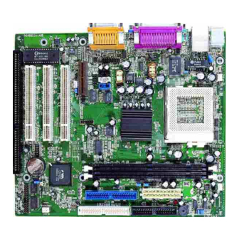
- Page 62 Mainboard Layout Mainboard Layout Note: The layout includes all options. It is for your reference only.
- Page 63 Caution Be sure to unplug the AC power supply before adding or removing expansion cards or other system peripherals, especially the CPU and SDRAM memory, otherwise your mainboard or the system memory might be seriously damaged. Caution Be sure to add some Silicone Grease between the CPU and the heatsink to keep them fully contacted to meet the heat sink requirement.
- Page 64 Note: This manual is suitable for Advance 6T series of motherboards. Each motherboard is carefully designed for the PC user who wants diverse features. Advance 6T: without onboard LAN Advance 6T-L: with onboard LAN The onboard LAN descriptions in the manual is invalid for...
Need help?
Do you have a question about the Advance 6T and is the answer not in the manual?
Questions and answers