Table of Contents
Advertisement
Declaration of conformity
QUANTUM DESIGNS(HK) LTD.
5/F Somerset House, TaiKoo Place 979 Kings Road,
(reference to the specification under which conformity is declared in
accordance with 89/336 EEC-EMC Directive)
þ
EN 55022
Limits and methods of measurements of radio disturbance
characteristics of information technology equipment
þ
EN 50081-1
Generic emission standard Part 1:
Residential, commercial and light industry
þ
EN 50082-1
Generic immunity standard Part 1:
Residential, commercial and light industry
European Representative:
QDI COMPUTER ( UK ) LTD
QDI SYSTEM HANDEL GMBH
QDI COMPUTER (FRANCE) SARL
QDI COMPUTER (ESPANA) S.A.
Signature :
Anders Cheung
Printed Name :
Quarry Bay, Hong Kong
declares that the product
Mainboard
KinetiZ 7T
is in conformity with
QDI COMPUTER ( SCANDINAVIA ) A/S
QDI COMPUTER ( NETHERLANDS) B. V.
QDI COMPUTER HANDELS GMBH
QDI COMPUTER (SWEDEN) AB
Place / Date :
Position/ Title :
HONG KONG/2000
President
Advertisement
Table of Contents

Related Manuals for QDI KinetiZ 7T


Summary of Contents for QDI KinetiZ 7T
-
Page 1: Declaration Of Conformity
EN 50082-1 Generic immunity standard Part 1: Residential, commercial and light industry European Representative: QDI COMPUTER ( UK ) LTD QDI COMPUTER ( SCANDINAVIA ) A/S QDI SYSTEM HANDEL GMBH QDI COMPUTER ( NETHERLANDS) B. V. QDI COMPUTER (FRANCE) SARL QDI COMPUTER HANDELS GMBH QDI COMPUTER (ESPANA) S.A. - Page 2 Declaration of conformity Trade Name: QDI Computer ( U. S . A. ) Inc. Model Name: KinetiZ 7T Responsible Party: QDI Computer ( U. S. A.) Inc. Address: 41456 Christy Street Fremont, CA 94538 Telephone: (510) 668-4933 Facsimile: (510) 668-4966...
-
Page 3: Table Of Contents
C O N T E N T S Facilité de vitesse Initialisation(Francais) ..........1 1. Introduction ..............Overview .................... 3 Key Features ..................3 Introduction to New Features .............. 5 2. Installation Instructions ..........External Connectors ..............7 PS/2 Keyboard & PS/2 Mouse Connector ..........7 USB1 &... - Page 4 PnP/PCI Configurations Setup .............. 30 PC Health Status .................. 31 Set Supervisor/User Password ............. 33 Boot with BIOS defaults ..............33 Appendix A QDI Driver CD 2000 ..........35 Appendix B ............ Boot Logo RecoveryEasy ..............39 Introduction ................... 39 Operation Process ................
- Page 5 Caution 1. Be sure to add some Silicone Grease between the Socket A pro- cessor and FAN to keep them fully contact, meanwhile to meet the heat sink requirement. 2. because the processor could overheat and damage both the proces- sor and the motherboard, we recommend that you should have an AMD authorized fan to prevent overheating.
- Page 6 KinetiZ 7A...
- Page 8 -- This page is intentionally left blank --...
-
Page 9: Introduction
Chapter 1 Chapter 1 Chapter 1 Introduction Introduction Overview The KinetiZ 7T green mainboard utilizes the VIA Apollo KT-133 chipset, providing a cost- effective PC/ATX platform with perfect capability and high performance to support Socket A AMD ® Duron /Athlon processors. - Page 10 Introduction Supports “Ultra DMA/33”Synchronous DMA mode transferring up to 33 Mbytes/sec. Supports “Ultra DMA/66”Synchronous DMA mode transferring up to 66 Mbytes/sec. Integrated 16x32bit buffer for IDE PCI Burst Transfers. On-chip I/O One floppy port supporting up to two 3.5 or 5.25 floppy drives with 360K/720K/1.2M/1.44M/2.88M format.
- Page 11 Chapter 1 supports system monitoring (monitors system temperature, CPU temperature, voltages, chassis intrusion and fan speed). Provides management application such as ManageEasy. Protects the system BIOS from being attacked by severe virus such as CIH, by enabling “BIOS-ProtectEasy” in CMOS setup or closing the Jumper “JAV”. BIOS Licensed advanced AWARD BIOS, supports flash ROM with 2M bit memory size, plug and play ready.
-
Page 12: Introduction To New Features
Ultra ATA/66 mode: The system board must have a special Ultra ATA/66 detect circuit, such as KinetiZ 7T mainboard. The system BIOS must also support Ultra ATA/66. The operating system must be capable of DMA transfers. Win95 (OSR2), Win98 and WindowsNT are capable. - Page 13 Introduction Chapter 1 PC-133 Memory PC133 SDRAM Unbuffered DIMM defines the electrical and mechanical requirements for 168-pin, 3.3 Volt, 133MHz, 64/72-bit wide, Unbuffered Synchronous DRAM Dual In-Line Memory Modules (SDRAM DIMMs). Relatively , the peak bandwidth of PC-133 memory is the 33% higher than PC-100 memory.
- Page 14 MIDI and wave sounds in two speakers. Full duplex operation also allows simultaneous audio recording and play- back. The KinetiZ 7T mainboard has two solution for on-board sound. Soft-sound(AC’97codec) Hardware-sound(CT5880)(Option) Note: If Creative ®...
-
Page 15: Installation Instructions
chapter 2 Chapter 2 Chapter 2 Installation Instructions Installation Instructions This section covers External Connectors and Jumper Settings. Refer to the mainboard layout chart for locations of all jumpers, external connectors, slots and I/O ports. Further- more, this section lists all necessary connector pin assignments for your reference. The particular state of the jumpers, connectors and ports are illustrated in the following figures. -
Page 16: Parallel Port Connector And Serial Port Connector
Installation Instruction Parallel Port Connector and Serial Port Connector (UART1) The parallel port connector can be connected to a parallel device such as a printer, while the serial port connector can be connected to a serial port device such as a serial port mouse. -
Page 17: Atx Power Supply Connector & Power Switch(Power Sw)
chapter 2 ATX Power Supply Connector & Power Switch (POWER SW) Be sure to connect the power supply plug to this connector in its proper orientation. The power switch (POWER SW) should be connected to a momentary switch (power button). When powering up your system, first turn on the mechanical switch of the power supply (if one is provided), then push once the power button. -
Page 18: Power Led Connector(Pwr_Led)
Installation Instruction Power LED Connector (PWRLED) The power LED has four status. When the system is in power up status, the LED is on. When the system is in suspend status, the LED is blink. When the system is in Suspend to RAM, the LED is off. -
Page 19: Internal Audio Connectors(Aux,Cdlin, Modem)
chapter 2 Internal Audio Connectors (AUX, CDLIN, MODEM) AUX and CDLIN connectors allow you to receive stereo audio input from such sound sources as a CD-ROM, TV tuner, or MPEG card. The MODEM connector allows the onboard audio to interface with a voice modem card with a similar connector. It also allows the sharing of mono_in (such as a phone) and mono_out (such as a speaker) between the onboard audio and the voice modem card. -
Page 20: Wake-Up On Lan (Wol)
Installation Instruction Wake-Up On Internal Modem (WOM) Through the Wake-Up On Internal Modem function, the system which is in the power-off status can be powered on by a ring signal received from the internal modem. If this function is to be used, be sure an internal modem card which supports the function is used. Then connect this header to the relevant connector on the modem card, set “Wake Up On LAN/ Ring ”... -
Page 21: Expansion Slots & I/O Ports Description
chapter 2 Expansion Slots & I/O Ports description Slot / Port Description PCI 1 First PCI slot. PCI 2 Second PCI slot. PCI 3 Third PCI slot. PCI 4 Fourth PCI slot. PCI 5 Fifth PCI slot. DIMM1 First DIMM slot. DIMM2 Second DIMM slot. -
Page 22: Clear Cmos(Jcc)
Installation Instruction Enable/Disable on-board audio(JSD) If you want to use the on-board audio, set JSD with pin2 & pin3 closed (default). Otherwise, set JSD with pin1 & pin2 closed for disabling this function. Enable on-board audio: Disable on-board audio: Clear CMOS (JCC) If you want to clear CMOS, unplug the AC power supply first, close JCC (pin1 &... -
Page 23: Overclocking Jumper Setting (Jfsb)
chapter 2 Setting the jumper JAV as open(default), meanwhile disabling the “BIOS_ProtectEasy” item from “Advanced BIOS Features” in AWARD BIOS CMOS Setup, allows you to flash the BIOS to the Flash ROM. The DMI (Desktop Management Interface) system information such as the CPU type/speed, memory size, and expansion cards will be detected by the onboard BIOS and stored in the flash ROM. - Page 24 -- This page is intentionally left blank --...
-
Page 25: Bios Description
1. Create a bootable system floppy diskette by typing Format A:/s from the DOS prompt under DOS6.xx or Windows 9x environment. 2. Click “Browse CD” option under QDI Driver CD 2000, copy Awdflash.exe (version>7.36) from the directory \Utility onto your new bootable diskette. -
Page 26: Award Bios Description
BIOS Description AWARD BIOS Description Entering Setup Power on the computer, when the following message briefly appears at the bottom of the screen during the POST (Power On Self Test), press <Del> key or simultaneously press the <Ctrl> + <Alt> + <Esc> keys, to enter the AWARD BIOS CMOS Setup Utility. Press <Del>... - Page 27 Chapter 3 Figure-2 Standard CMOS Setup Menu For the items marked, press enter, a window will pop up as shown below. You can view detailed information or make modifications. Figure-2-1 IDE Primary Master Setup Menu Hard Disk Primary Master/Primary Slave/Secondary Master/Secondary Slave These categories identify the HDD types of 2 IDE channels installed in the computer system.
- Page 28 BIOS Description The Award BIOS supports 3 HDD modes: NORMAL, LBA and LARGE. NORMAL Generic access mode in which neither the BIOS nor the IDE controller will make any trans- formation during accessing. The maximum number of cylinders, heads and sectors for NORMAL mode are 1024,16 and 63.
- Page 29 Chapter 3 Video Set this field to the type of video display card installed in your system. EGA/ VGA Enhanced Graphics Adapter / Video Graphic Array. For EGA, VGA, SEGA, SVGA, or PGA monitor adapters. CGA 40 Color Graphic Adapter, powering up in 40 column mode. CGA 80 Color Graphic Adapter, powering up in 80 column mode.
-
Page 30: Frequency/Voltage Control
BIOS Description Frequency/Voltage Control Figure-9 Frequency/Voltage Control Menu The following indicates the options for each item and describes their meaning. Item Option Description Auto Detect DIMM/ Enabled Closes the CLK signal if no PCI or DIMM PCI Clk Disabled plug in. CPU Host/PCI/ Default These items are of selected CPU FSB... -
Page 31: Advanced Bios Features Setup
Chapter 3 Advanced BIOS Features Setup Figure-3 Advanced BIOS Features Setup Menu The following indicates the options for each item and describes their meaning. Item Option Description Anti-Virus Enabled Allows you to choose the VIRUS warning feature Protection for IDE Hard Disk boot sector protection. If this function is enabled and someone attempt to write data into this area, BIOS will show a warning message on screen and alarm beep. - Page 32 BIOS Description Boot Up Enabled Tests floppy drives to determine whether they Floppy Seek Disabled have 40 or 80 tracks. Boot Up Keypad is used as number keys. Numlock Status Keypad is used as arrow keys. Gate A20 Normal The A20 signal is controlled by the keyboard controller Option or chipset hardware.
-
Page 33: Advanced Chipset Features Setup
Chapter 3 Advanced Chipset Features Setup Figure-4 Advanced Chipset Features Setup Menu The following indicates the options for each item and describes their meaning. Item Option Description Bank 0/1, 2/3, 4/5 SDRAM 8/10ns These items are of selected SDRAM read/write DRAM Timing Normal timing. - Page 34 BIOS Description System BIOS Enabled Besides conventioal memory, system BIOS area Cacheable is also cacheable. Disabled System BIOS area is not cacheable. Video RAM Enabled Besides conventional memory, video RAM is also Cacheable also cacheable. Disabled Video RAM area is not cacheable. AGP Aperture Size 4~128 Sets the effective size of the Graphics Aperture...
-
Page 35: Integrated Peripherals
Chapter 3 BIOS Description Integrated Peripherals Figure-5 Integrated Peripherals Menu The following indicates the options for each item and describes their meaning. Item Option Description OnChip IDE Enabled Enables OnChip IDE First/Second Channel. channel 0/1 Disabled Disables OnChip IDE First/Second Channel. IDE Prefetch Mode Enabled Enables IDE Prefetch Mode. - Page 36 BIOS Description UART 2 Mode Standard Defines Serial Port 2 as standard serial port. HPSIR Supports IRD mode. ASKIR Supports SHARP ASK-IR protocol with maximum baud rate up to 57600bps. Onboard Parallel 378/IRQ7, Defines onboard parallel port address and IRQ Port 278/IRQ5, channel.
-
Page 37: Power Management Setup
Chapter 3 Power Management Setup Figure-6 Power Management Setup Menu The following indicates the options for each item and describes their meaning. Item Option Description ACPI function Enabled Validates ACPI function. Disabled Invalidates ACPI function. Power User Define Users can configure their own Power Management Management Timer. - Page 38 BIOS Description Modem Use IRQ 3,5,7,9,10,11 Special Wake-up event for Modem. Soft-off by Instant-off The system will power off immediately once the PWRBTN power button is pressed. Delay 4 Sec The system will not power off until the power button has been pressed continuously for more than 4 seconds.
-
Page 39: Pnp/Pci Configurations Setup
Chapter 3 BIOS Description PnP/PCI Configurations Setup Figure-7 PnP/PCI Configurations Setup Menu The following indicates the options for each item and describes their meaning. Item Option Description PNP OS Installed Device resources assigned by PnP OS. Device resources assigned by BIOS. Reset Configuration Enabled The system BIOS will reset configuration data... -
Page 40: Pc Health Status
BIOS Description PC Health Status Figure-8 PC Health Status Menu The following describes the meaning of each item. Item Current Description Data Shown Current CPU Temp C/102 Temperature of the CPU core. Current System Temp. C/ 86 Temperature inside the chassis. Current CPUFAN Speed 3999RPM RPM( Revolution Per Minute) speed of fan... -
Page 41: Set Supervisor/User Password
BIOS Description Set Supervisor/ User Password When this function is selected, the following message appears at the center of the screen to assist you in creating a password. ENTER PASSWORD Type the password, up to eight characters, and press <Enter>. The password typed now will clear any previously entered password from CMOS memory. - Page 42 QDI Driver CD 2000 QDI Driver CD 2000 A QDI Driver CD 2000 is supplied with this mainboard. Insert CD 2000 that came with your mainboard into your CD-ROM drive to bring up the screen, click the options to install. The contents contained in it are showed as below: 1.
- Page 43 Today, it is possible to monitor and manage your complex hardware from Windows 9X and Windows NT. QDI ManageEasy is a system tool, a bridge between the complex hardware and OS, used to access hardware status and to execute control functions. It supports stronger functions for Windows 9X and Windows NT.
- Page 44 If you don’t prefer the logo displayed on the screen during boot up, set the “Show Bootup Logo” option as Disabled in the “BIOS FEATURES SETUP” section of the BIOS. * We reserve the right of modifying the default full-logo of QDI without further notification.
-
Page 45: Recoveryeasy
Introduction: RecoveryEasy , the latest QDI innovation, is able to protect the system from being de- stroyed, by creating a so-called “mirror partition” for a current hard disk partition and backuping all the data to the mirror area. This ideal utility provides disk partition, disk data backup/recovery, CMOS settings backup/recovery and multi-boot functions. - Page 46 RecoveryEasy b. If choosing to install RecoveryEasy on an absolutely clear disk, the utility will delete all the previous partitions. c. The password is set as default setting “qdiqdi” after installing RecoveryEasy. 1.1 CREATE PAR Function : Creates a new partition. Limitation : When no disk space remains or 4 partitions already exist, this button is disabled.
- Page 47 RecoveryEasy 1.3 ACTIVE PAR Function : Implements multi-boot function by activating one of the partitions. Limitation : When no partition exists, this button is disabled. Steps : If there’re two or more partitions, choose one of them by pressing F5 key. Note : After setting active partition, a letter “A”...
- Page 48 RecoveryEasy a. When two or more than two hard disks are installed on the system, use F5 key to choose the hard disk. Every time users use F5 key to switch the hard disk, the operation result for the previous hard disk is saved. When processing a certain hard disk, F5 key can be used to choose the partition.
- Page 49 KinetiZ 7A Note: a. During the process of partition backup or recovery, a guage will be shown as below, the backup or recovery speed is about 4-5Mbyte/s. See figure-4. figure-4 Backup Partition b. If a disk I/O error occurs during the process of partition backup or recovery, this means there’s physical damage on the hard disk, however users can ignore it and continue the process.
-
Page 50: Faq
RecoveryEasy 2.6 CHANGE PWD Function : Changes the password to enter RecoveryEasy Partition or Recovery User Interface. Limitation : None. Steps : Follow the system prompt, input the password no more than 6 characters twice. To delete the password, follow the system prompt and press the “Enter”... - Page 51 RecoveryEasy Are there any hard disk limitations of RecoveryEasy? RecoveryEasy supports all kinds of current IDE hard disks and has no limitation on the hard disk capacity. RecoveryEasy can not provide its function for some special hard disk types such as SCSI, but it will not affect their usage. Are there any OS limitations of RecoveryEasy? RecoveryEasy supports current operating systems such as DOS, Windows 95/98.
- Page 52 RecoveryEasy before converting can avoid this problem. It’s the same situation as “FAT32 Converter” provided in Windows98. What if partitions be wrongly deleted in RecoveryEasy? If users delete a partition in RecoveryEasy by mistake, they can save it by pressing the Reset button on their system at once. Do not press the “ESC” key to quit RecoveryEasy, this will save the change.
- Page 53 Item Checklist Completely check your package. If you discover damaged or missing items, contact your retailer. KinetiZ 7T mainboard QDI Driver CD 2000 I/O shield 1 IDE ribbon cable 1 floppy ribbon cable 1 10-pin ribbon cable with bracket for USB3 and USB4(manufacturing option) User’s manual...
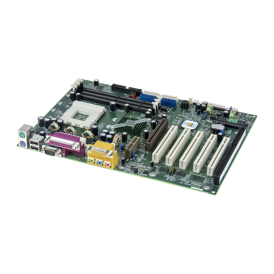
- Page 54 Board Layout of Board Layout of KinetiZ 7T V1.0 KinetiZ 7T V1.0 P/N: 430-01021-801-00 Manual for KinetiZ 7T Ver 1.0...