Table of Contents
Advertisement
Item Checklist
This item checklist is only available for retail market.
Completely check your package,If you discover dam-
aged or missing items, contact your retailer.
P4I848P series mainboard
QDI Utility CD
1HD ribbon cable
1 FDD cable
User's manual
I/O shield
1 10-pin ribbom cable with bracket for USB(option)
Cable with bracket for 6CH_BRACKET(option)
Signal cables for Serial ATA(option)
Power cables for Serial ATA(option)
Notice
The information in this document is subject to
change in order to improve reliability, design, or func-
tion without prior notice and does not represent a
commitment on the part of this company. In no event
will we be liable for direct, indirect, special, inciden-
tal, or consequential damages arising out of the use
or the possibility of such damages.
All trademarks are the property of their respective
owners.
If you need any further information, please visit our
web-site: "www.qdigrp.com".
Advertisement
Table of Contents

Related Manuals for QDI P4I848P


Summary of Contents for QDI P4I848P
-
Page 1: Item Checklist
Item Checklist This item checklist is only available for retail market. Completely check your package,If you discover dam- aged or missing items, contact your retailer. P4I848P series mainboard QDI Utility CD 1HD ribbon cable 1 FDD cable User’s manual I/O shield... -
Page 2: Declaration Of Conformity
Residential, commercial and light industry EN 50082-1 Generic immunity standard Part 1: Residential, commercial and light industry European Representative: QDI COMPUTER ( UK ) LTD QDI COMPUTER ( SCANDINAVIA ) A/S QDI SYSTEM HANDEL GMBH QDI EUROPE B. V. QDI COMPUTER (FRANCE) SARL QDI COMPUTER HANDELS GMBH LEGEND QDI SPAIN S.L... - Page 3 Declaration of conformity Trade Name: QDI Computer ( U. S . A. ) Inc. Model Name: P4I848P Responsible Party: QDI Computer ( U. S. A.) Inc. Address: 41456 Christy Street Fremont, CA 94538 Telephone: (510) 668-4933 Facsimile: (510) 668-4966 Equipment Classification:...
-
Page 4: Table Of Contents
Chapter 1 Introduction ..............1 Key Features ..............2 Chapter 2 Installation Instructions............5 External Connectors ............6 PS/2 Keyboard /Mouse Connector ........6 USB1, USB2,USB3,USB4 and LAN Connectors ....6 Parallel Port, Serial Port and SPDIF Connectors ....6 1394 Port................7 Line-in jack, Mic-in jack and Speaker-out jack .... - Page 5 Wake-up function(JUSB, JFUSB)(optional) (optional) Onboard LAN(LAN_EN)..............21...
- Page 6 Caution Be sure to unplug the AC power supply before adding or re- moving expansion cards, RAM or other system peripherals, other- wise your mainboard and RAM might be seriously damaged. Caution Be sure to add some Silicone Grease between the CPU and the heatsink to keep them fully contacted to meet the heat sink require- ment.
- Page 8 T-- This page is intentionally left blank --his...
-
Page 9: Chapter 1 Introduction
Chapter 1 Chapter 1 Chapter 1 Chapter 1 Introduction P4I848P series of mainboards utilize Intel 848P + ICH5 ® (ICH5R) chipset, providing a fully compatible, high perfor- mance and cost-effective ATX platform. The new integrated technologies, together with AC’97 audio(2/6-channel), 8 USB, 2 SATA, and ATA100/66/33, give customers an advanced, multimedia solution at reasonable price. -
Page 10: Key Features
Introduction Introduction Introduction Introduction Introduction Key Features Form factor ATX form factor of 305mm x 210mm Microprocessor Supports Intel ® Pentium 4 (Hyper-Threading) socket 478 processors Supports Intel ® Pentium 4 (Northwood) socket 478 processors at 2.4/2.6/2.8/3.06/3.2GHz with 800 MHz FSB Supports Intel Pentium 4 (Northwood) socket 478 processors at 1.8/2.0/2.2/2.26/2.4/2.53/2.66 ®... -
Page 11: Onboard Audio
(Reference to “PC Health Status” in BIOS) Supports hot-plug Two SATA devices including SATA HDD and CDROM/DVD ROM devices Supports 150Mbps transfer rate. BIOS Licensed advanced AWARD(Phoenix) BIOS, supports flash ROM, plug and play ready Supports IDE CDROM/SCSI/USB boot up. P4I848P P4I848P P4I848P P4I848P P4I848P... - Page 12 Introduction Introduction Introduction Introduction Introduction Green function Supports ACPI (Advanced Configuration and Power Interface) and ODPM (OS Directed Power Management) Supports ACPI power status: S0 (full-on), S1 (power on suspend), S3 (suspend to RAM), S4(suspend to Disk, depends on OS) and S5 (soft-off) Main Expansion Slots and Connectors Slot/Port (Quantity) Description...
-
Page 13: Installation Instructions
The particular state of the jumpers, connectors and ports are illustrated in the follow- ing figures. Before setting the jumpers or inserting these connectors, please pay attention to the direction. P4I848P P4I848P P4I848P P4I848P P4I848P... -
Page 14: External Connectors
Installation Instr Installation Instr Installation Instruction Installation Instr Installation Instr uction uction uction uction External Connectors PS/2 Keyboard/Mouse Connector PS/2 keyboard connector is for the usage of PS/2 keyboard. If using a standard AT size keyboard, an adapter should be used to fit this connector. PS/2 mouse connector is for the usage of PS/2 mouse. -
Page 15: 1394 Port
If set 2-Channel Audio mode on -6A mainboard, you can connect two speakers to the Front Left&Right jack, at the same time use the Rear Left&Right jack as Line in jack, and use the Center&Woofer jack as Microphone in jack. P4I848P P4I848P P4I848P... -
Page 16: Atx 12V Power Supply Connectors & Power Switch
Installation Instr Installation Instr Installation Instruction Installation Instr Installation Instr uction uction uction uction ATX 12V Power Supply Connector & Power Switch (POWER SW) The power switch (POWER SW) should be connected to a momentary switch. When powering up your system, first turn on the mechanical switch of the power supply (if one is provided), then push once the power switch. -
Page 17: Speaker Connector (Speaker)
LED is green blink. When the system is in S3 status, the LED is orange on. When the system is in S4, S5 status, the LED is off. ORANGE(-) GREEN(-) LED+(VCC) SPKDATA RESET POWER HDD LED(-) LED- LED+ HDD LED(+) P4I848P P4I848P P4I848P P4I848P P4I848P... -
Page 18: Usb35,6; Usb7,8 Connector
USB5,6; USB7,8 Besides USB1,2,3,4 on the back panel, P4I848P series of mainboards also have two 8-pin headers on board which may connect to front panel USB cable( optional ) to provide additional four USB ports. USB7,8 USB5,6 Infrared Header (IrDA) This connector supports wireless transmitting and receiving device. -
Page 19: Fan Connectors( Cpu_Fan , Pwr_Fan )
“Power on by Ring/LAN” as Enabled in the “Power Management Setup” section of the CMOS SETUP. Save and exit, then boot the operating system once to make sure this function takes effect. +5V standby Signal for waking up(active low) P4I848P P4I848P P4I848P P4I848P P4I848P... -
Page 20: Audio Connectors (Cd_In, Aux_In, Modem)
Installation Instr Installation Instr Installation Instruction Installation Instr Installation Instr uction uction uction uction Audio Connectors (CD_IN, AUX_IN, MODEM) (Available on -6A mainboard) CD_IN CD Left Channel CD Right Channel AUX_IN Right Audio Channel Left Audio Channel MODEM Mono-Out (to Modem) Phone-In (from Modem) 4-pin SMBus Connector(SMBUS) This connector allows you to connect SMBus devices. -
Page 21: Diagnosis Led
CPU damaged , BIOS chip absent or damaged system detect CPU and initialize chipset system detect memory system initialize PCI system initialize clockgen system detect Video and invoke Video BIOS Hyper-Threading OK LED1 LED2 LED3 LED4 LED5 P4I848P P4I848P P4I848P P4I848P P4I848P... -
Page 22: Front Audio Interface(F_Audio)
Installation Instr Installation Instr Installation Instruction Installation Instr Installation Instr uction uction uction uction Front Audio Interface(F_Audio) The audio interface provides two kinds of audio output choices: the FrontAudio, the RearAudio. Their priority level is as sequence. When the FrontAudio is available, the RearAudio will be cut off. -
Page 23: 6Ch-Bracket Connector
If the connector has been closed once, the system will record the status and indicate the chassis has been opened. You can monitor or check this information from some software. CHSSEC Indicate signal P4I848P P4I848P P4I848P P4I848P P4I848P... -
Page 24: Front Ieee 1394 Port(F_1394)
Installation Instr Installation Instr Installation Instruction Installation Instr Installation Instr uction uction uction uction Front IEEE 1394 port(F_1394) Besides one 1394 port on the back panel, the mainboard also have one 10-pin headers on board to provide additional IEEE 1394 port. F_1394 TPA+ TPA-... -
Page 25: Jumper Settings
& pin3 closed for disabling. Furthermore, the item “Wake-Up From S3 by USB”in Power Management Setup should also be set correspondingly to enable or disable this function. JUSB 1 2 3 1 2 3 Enable Disable (default) JFUSB Disable Enable (default) P4I848P P4I848P P4I848P P4I848P P4I848P... - Page 26 For bus ratio unlocked processor, this overclocking feature can be implemented by setting FSB as 100x4/133x4/166x4/200x4MHz, meanwhile adjusting the bus ratio (multi- plier) in “QDI Innovation features” in AWARD BIOS CMOS Setup and memorry. Warning: Be sure your selection is right. CPU over speeding is dangerous! We...
- Page 27 DMI information impossible. Therefore, set BIOS_WP as open when changing the system hardware configuration, or the error message “Unknown Flash Type” will be dis- played on the screen, and DMI information may not be updated. P4I848P P4I848P P4I848P...
- Page 28 Installation Instr Installation Instr Installation Instruction Installation Instr Installation Instr uction uction uction uction Enable keyboard password power-on function (JKB) The mainboard provides the advanced keyboard password power-on function. Before using this function, set JKB with pin1 & pin2 closed. Otherwise, set JKB with pin2 & pin3 closed for disabling.
- Page 29 (Unplug the AC power supply) Onboard LAN (LAN_EN) If you want to use the onboard LAN, set LAN_EN with pin1&pin2 closed, Otherwise, set LAN_EN with pin2&pin3 closed for disable this fuction. Disable onboard LAN LAN_EN Enable onboard LAN P4I848P P4I848P P4I848P P4I848P P4I848P...
- Page 30 T-- This page is intentionally left blank --his...
-
Page 31: Bios Description
Setup utility for users to modify the basic sys- tem configuration. The information is stored in CMOS RAM so it retains the Setup information when the power is turned off. This chapter provides you with the over- view of the BIOS Setup. P4I848P P4I848P P4I848P P4I848P P4I848P... - Page 32 1. Create a bootable system floppy diskette by typing Format A:/s from the DOS prompt under DOS6.xx or Windows 9x environment. 2. Copy AWDFLASH.EXE(version>=8 .24q) from the directory \Utility located on QDI Driver CD to your new bootable diskette. 3. Download the updated BIOS file from the Website (http://www.qdigrp.com). Please be sure to download the suitable BIOS file for your motherboard.
-
Page 33: Award Bios Description
The basic CMOS settings included in “Standard CMOS Features” are Date, Time, Hard Disk Drive Types, Floppy Disk Drive Types, and VGA etc. Use the arrow keys to highlight the item, then use the <PgUp> or <PgDn> keys to select the value desired in each item. P4I848P P4I848P P4I848P... - Page 34 BIOS Description BIOS Description BIOS Description BIOS Description BIOS Description Figure-2 Standard CMOS Setup Menu For the items marked, press enter, a window will pop up as shown below. You can view detailed information or make modifications. Figure-2-1 IDE Primary Master Setup Menu Hard Disk Primary Master/Primary Slave/Secondary Master/Secondary Slave These categories identify the HDD types of 2 IDE channels installed in the computer system.
- Page 35 To support LBA or LARGE mode of HDDs, there must be some softwares involved which are located in Award HDD Service Routine(INT13h).It may fail to access a HDD with LBA (LARGE) mode selected if you are running under an Operating System which replaces the whole INT 13h. P4I848P P4I848P P4I848P P4I848P...
- Page 36 BIOS Description BIOS Description BIOS Description BIOS Description BIOS Description Video Set this field to the type of video display card installed in your system. EGA/ VGA Enhanced Graphics Adapter / Video Graphic Array. For EGA, VGA, SEGA, SVGA or PGA monitor adapters. CGA 40 Color Graphic Adapter, powering up in 40 column mode.
- Page 37 Chapter 3 Chapter 3 Chapter 3 Chapter 3 Chapter 3 QDI Innovation Features Figure-3 QDI Innovation features Menu The following indicates the options for each item and describes their meaning. Item Option Description [SpeedEasy setting] CPU Clock Ratio Min=8 Select the multiplication of processor core frequency. If...
- Page 38 BIOS Description BIOS Description BIOS Description BIOS Description BIOS Description [RecoveryEasyII setting] Menu language Select English Select RecoveryEasyII Interface Menu language. Chinese Hotkey for NULL Backup/Recovery interface can not be used by Backup/Recovery Pressing Hotkey. F2~F12 Select Hotkey to enter Backup/Recovery interface during POST.
-
Page 39: Advanced Bios Features Setup
Floppy, LS200, Hard Disk, CDROM, ZIP100, USB-FDD, Boot Other Device USB-ZIP,USB-CDROM,LAN Swap Floppy Drive Enabled If the system has two floppy drives, choose enable Disabled to assign physical drive B to logical drive Aand vice- P4I848P P4I848P P4I848P P4I848P P4I848P... - Page 40 BIOS Description BIOS Description BIOS Description BIOS Description BIOS Description Boot Up Keypad is used as number keys. NumLock Status Keypad is used as arrow keys. Gate A20 Option Normal The A20 signal is controlled by the keyboard controller. Fast The A20 signal is controlled by Port92.
-
Page 41: Advanced Chipset Features Setup
Set DRAM RAS# to CAS# delay 2 SCLKs,3 SCLKs CAS# Delay or 4 SCLKs. DRAM RAS#Precharge 2,3,4 Set DRAM RAS# precharge as 2,3 or 4. Memory Frequency Auto Set Memory Frequency DDR266 DDR320 DDR333 DDR400 P4I848P P4I848P P4I848P P4I848P P4I848P... - Page 42 BIOS Description BIOS Description BIOS Description BIOS Description BIOS Description System BIOS Enabled Besides conventional memory, the system BIOS area Cacheable is also cacheable. Disabled System BIOS area is not cacheable. Video BIOS Besides conventional memory, video BIOS area is Enabled Cacheable also cacheable.
-
Page 43: Power Management Setup
Blank DPMS V-SYNC & H - SYNC signals from VGA card to monitor. This function is enabled only for VGA cards supporting DPMS. Note: When the green monitor does not detect the V/H-SYNC signals, the electron gun will be turned off. P4I848P P4I848P P4I848P P4I848P P4I848P... - Page 44 BIOS Description BIOS Description BIOS Description BIOS Description BIOS Description Video Off In The system will disable video when entering suspend Suspend mode. Do not turn off video when entering suspend mode. Suspend Type Stop Grant Select the Suspend type. PwrOn Suspend MODEM Use 3,4,5,7,9,10,11 Special Wake-up event for Modem.
- Page 45 Reload global timer, when there’s a FDD/COM/LPT event. Port Disabled Do not reload global timer. PCI PIRQ[A - D] # Enabled Reload global timer, when there’s a PCI event. Disabled Do not reload global timer. P4I848P P4I848P P4I848P P4I848P P4I848P...
- Page 46 BIOS Description BIOS Description BIOS Description BIOS Description BIOS Description PNP/PCI Configurations Setup Figure-7 PNP/PCI Configurations Setup Menu The following indicates the options for each item and describes their meaning. Item Option Description Reset Configuration Enabled The system BIOS will reset configuration data once Data then automatically set this item as disabled.
-
Page 47: Integrated Peripherals
Secondary PCI IDE Disabled On-Chip Primary/Secondary PCI IDE is disabled. Mode 0 - 4 Define the IDE primary/secondary master/slave PIO Primary/ Secondary mode. Master/Slave PIO Auto The IDE PIO mode is defined by auto -detection. P4I848P P4I848P P4I848P P4I848P P4I848P... - Page 48 BIOS Description BIOS Description BIOS Description BIOS Description BIOS Description Disable this function. USB/USB2.0 Enabled Enable onchip USB controller. Controller Disabled Disable onchip USB controller. USB Keyboard/ Enabled Support USB Keyboard under legacy OS. Mouse Support Disabled Do not support USB Keyboard under legacy OS. AC97 Audio Auto If audio codec was installed on board, the AC97 Audio...
- Page 49 Parallel Port Mode SPP Define the parallel port mode. ECP+EPP Normal EPP Mode Select EPP1.7 Set EPP Mode as EPP 1.7 or EPP1.9 Version. EPP1.9 ECP Mode Use Set ECP Mode Use DMA 1 or 3. P4I848P P4I848P P4I848P P4I848P P4I848P...
- Page 50 BIOS Description BIOS Description BIOS Description BIOS Description BIOS Description PWRON After OFF,ON The system remains OFF/ON/Former state when the AC PWR-Fail Former-Sts power supply resumes.
-
Page 51: Pc Health Status
C/176 F, 85 C/185 F,90 C/194 F, 95 C/145 C/151 C/158 C/167 C/176 C/185 C/194 C/205 Disabled No alarm beep. Current System The temperature inside the chassis. Temp. Current CPU The temperature of CPU. Temperature P4I848P P4I848P P4I848P P4I848P P4I848P... - Page 52 BIOS Description BIOS Description BIOS Description BIOS Description BIOS Description Current PWRFAN RPM (Revolution Per Minute) Speed of fan which is Speed connected to the fan header, CPUFAN or PWRFAN. Current CPUFAN Fan speed value is based on an assumption that Speed tachometer signal is two pulses per revolution.
-
Page 53: Password Setting
If you have made all the changes to CMOS values and the system can not boot with the CMOS values selected in setup, clear CMOS after power-down, then power on again. System will boot with BIOS default settings. P4I848P P4I848P P4I848P... - Page 54 QDI Utility CD A QDI Utility CD is supplied with this mainboard, the contents contained in it are showed as below: 1. Driver Install Using this choice, you can install all the drivers for your mainboard . You should install the drivers in order, and you need to restart your computer until all the drivers are installed.
- Page 55 LogoEasy II Thank you for using QDI upgraded innovation--- LogoEasy II, which is completely compat- ible with LOGOEASY. LOGOEASY II can be easily operated in a Windows environment, following in steps with the trend. It has added the functions of supporting JPEG images and true color display of 64K and 16M colors with regard to JPEG-format graphics files and the high-precision display equipment, which are now widely used.
- Page 56 Appendix A. Using CBLOGO.EXE Utility (Under DOS ): 1. Copy “CBLOGO.EXE”and “AWDFLASH.EXE” from the directory \Utility located on QDI Driver CD to your hard disk. 2. Get the BIOS file from “AWDFLASH.EXE” or Download the BIOS file from the Website (http://www.qdigrp.com) and copy the BIOS file(xxxxxx.bin) to your hard disk.
- Page 57 (1) Multiform partition format can be supported in RecoveryEasy II, including FAT16, FAT32, NTFS etc. (2) The capability of supportable Hard Disk is up to 137GB. Flexible Combination The hard disk data can be choosed to be protected and restored as required. P4I848P P4I848P P4I848P P4I848P P4I848P...
- Page 58 Please press “DEL” key to enter CMOS setup during the POST(Power On Self Test), then user can see [RecoveryEasyII Setting] items of the “QDI Innovation features” menu, in which the language on RecoveryEasyII interface and hotkey could be selected .
- Page 59 Press ENTER to confirm. 1 Backup Partition Table 2 Backup System Partition C: 3 Backup Whole Disk 4 Backup CMOS Setup 5 Free Backup Area 6 Exit Backup Menu figure-3 Backup Interface P4I848P P4I848P P4I848P P4I848P P4I848P...
- Page 60 Appendix Appendix Appendix Appendix Appendix 1 Backup Partition Table 2 Backup System Partition It is used to backup the system partition of current hard disk. It makes a backup of the data in the bootable par- tition (actived partition) of current hard disk, as well as the partition table.
- Page 61 Hard Disk will be overwritten. 4.Recover CMOS Setup This will restore the latest backup of the CMOS Set- tings you have made to the current CMOS. figure-4 Recover process P4I848P P4I848P P4I848P P4I848P P4I848P...
- Page 62 5. Save and exit BIOS Setup, your system will now boot successfully. CPU SpeedEasy Setup Menu Select <QDI Innovation features> item from the main menu and enter the sub-menu: QDI Innovation features Menu BIOS provides you with a set of basic values for your processor selection instead of the jumper settings.
- Page 63 OS. BootEasy is quite easy to use , choose the right option in CMOS SETUP, ( refer to QDI Innovation features) it can be easily booted quickly. BootEasy save all the information when PC first normally boot-up, and it restores all the pa- rameters for the system and thus let the PC boot freely and rapidly.
-
Page 64: Installing The Audio Driver
Appendix Appendix Appendix Appendix Appendix Using 4/6-Channel Audio The motherboard is equipped with Realtek ALC655 chip, which provides support for 6-channel audio output, including 2 Front, 2 Rear, 1 Center and 1 Subwoofer channel. ALC655 allows the board to attach 4 or 6 speakers for better surround sound effect. The section will tell you how to install and use 4/6-channel audio function on the board. -
Page 65: Attaching Speakers
Selecting 4- or 6-Channel Setting later in the section. Make sure all speakers are connected to Line Out connectors. Diverse connector configura- tions for 2-, 4- and 6-channel using back panel connectors are described below: P4I848P P4I848P P4I848P... - Page 66 Appendix Appendix Appendix Appendix Appendix Description: Line Out, Line In and MIC functions all exist under 2-channel configuration. Description: Line In is converted to Line Out function under 4-channel configuration.
- Page 67 6-Channel Analog Audio Output Description: Both Line In and MIC are converted to Line Out function under 6-channel configuration. P4I848P P4I848P P4I848P P4I848P P4I848P...
- Page 68 Appendix Appendix Appendix Appendix Appendix Selecting 4- or 6-Channel Setting 1. Click the audio icon from the window tray at the bottom of the screen. 2. Select any surround sound effect you prefer from the “Environment” pull-down menu under the Sound Effect tab. 3.
-
Page 69: Testing The Connected Speakers
Testing Each Speaker 1. Click the audio icon from the window tray at the bottom of the screen. 2. Click the Speaker Test tab. P4I848P P4I848P P4I848P P4I848P P4I848P... -
Page 70: Playing Karaok
Appendix Appendix Appendix Appendix Appendix The following window appears. Select the speaker which you want to test by clicking on it. Playing KaraOK The KaraOK function will automatically remove human voice (lyrics) and leave melody for you to sing the song. The function is applied only for 2-channel audio operation, so make sure “2 channels mode”... - Page 71 3. Select Voice Cancellation in the “Karaoke” column. Click OK. P4I848P P4I848P P4I848P P4I848P P4I848P...
-
Page 72: Cpu Installation Procedures
Appendix Appendix Appendix Appendix Appendix CPU Installation Procedures 1. Pull the lever sideways away from the socket. Then, raise the lever up to a 90-degree angle. 2. Look for the cut edge. The cut edge should point towards the lever pivot. The CPU will only fit in the correct orientation. -
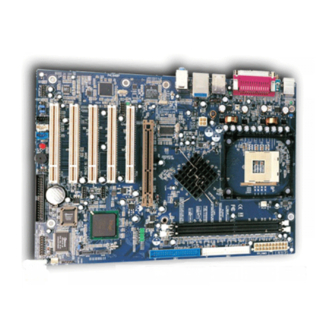
Page 73: Mainboard Layout
Mainboard Layout P4I848P Note: The layout includes all options. It is for your reference only. - Page 74 Top :PS/2 Mouse Bttm:PS/2 Keyboard SPDIF UART 1 Top :Line in Top :LAN(optional) Middle:Speaker out Bttm: USB3,4 Bttm:Mic. in Parallel Port Top :IEEE 1394(optional) Bttm: USB1,2 LAN_EN F_1394 ATX 12V CD_IN AUX_IN MODEM SMBUS North Bridge Socket 478 CPU_FAN South Bridge BIOS_WP DIMM1 DIMM2...
Need help?
Do you have a question about the P4I848P and is the answer not in the manual?
Questions and answers