Table of Contents
Advertisement
Quick Links
Item Checklist
This item checklist is only available for retail
market. Completely check your package, If you
discover damaged or missing items, contact
your retailer.
XT4500 series mainboard
QDI Utility CD
1HD ribbon cable
1 FDD cable
User' s manual
I/O shield(option)
USB cable(option)
Notice
The information in this document is subject to
change in order to improve reliability, design, or
function without prior notice and does not repre-
sent a commitment on the part of this company.
In no event will we be liable for direct, indirect,
special, incidental, or consequential damages
arising out of the use or the possibility of such
damages.
All trademarks are the property of their respec-
tive owners.
If you need any further information, please visit
our web-site: " www.qdigrp.com" .
Advertisement
Table of Contents

Related Manuals for QDI XT4500 Series


Summary of Contents for QDI XT4500 Series
- Page 1 Item Checklist This item checklist is only available for retail market. Completely check your package, If you discover damaged or missing items, contact your retailer. XT4500 series mainboard QDI Utility CD 1HD ribbon cable 1 FDD cable User’ s manual...
- Page 2 The following products have been tested by us with the listed standards and found in compliance with the council EMC directive 89/336/EEC. It is demonstrative for the compliance with this EMC Directive. Submittor: QDI Technology Limited 23Floor, Lincoln House, Taikoo Place 979 King’ s Road, Quarry Bay, HONG KONG Product:...
- Page 3 Declaration of conformity Trade Name: QDI Computer ( U. S . A. ) Inc. Model Name: XT4500 Responsible Party: QDI Computer ( U. S. A.) Inc. Address: 41456 Christy Street Fremont, CA 94538 Telephone: (510) 668-4933 Facsimile: (510) 668-4966 Equipment Classification:...
-
Page 4: Table Of Contents
Audio Connectors (CD_IN) ..........9 Audio Interface(F_AUDIO) ..........10 SPEAKER Connector ............10 Jumper Settings ..............11 Clear CMOS(CLR_CMOS)............ 11 Chapter 3 BIOS Description..............12 AWDFLASH.EXE ............... 13 AWARD BIOS Description..........14 Appendix QDI Utility CD..............16 Using 4-/6-Channel Audio..........25 Layout... - Page 5 Be sure to add some Silicone Grease between the CPU and the heatsink to keep them fully contacted to meet the heat sink requirement. Note: This manual is suitable for XT4500 series of mainboards. Each mainboard is carefully designed for the PC user who wants different features.
-
Page 6: Chapter 1 Introduction
Chapter 1 Chapter 1 Introduction XT4500 series of mainboards utilize Intel ® 845PE +ICH4 chipset, providing a fully compatible, high performance and cost-effective mATX platform. The new integrated technologies, together with AC’ 97 audio,AGP 4X, 4 USB 2.0 ports and ATA100/66/33, give customers an advanced, multi- media solution at reasonable price. -
Page 7: Key Features
Introduction Form factor mATX form factor of 244mm x 190mm Microprocessor ® Supports Intel Pentium 4 (Willamette) socket 478 processors at 1.4/1.5/1.6/1.7/1.8/ 1.9/2.0GHz ® Supports Intel Pentium 4 (Northwood) socket 478 processors at 1.6/1.8/2.0/2.2/ 2.4/2.6/2.8/3.06GHz Supports Prescott socket 478 processors of FSB 533MHz Supports 400/533MHz host bus speed System memory Supports DDR266/333 SDRAM... - Page 8 Chapter 1 Advanced features PCI 2.2 Specification Compliant Provides Trend ChipAwayVirus On Guard BIOS Licensed advanced AWARD(Phoenix) BIOS, supports flash ROM, plug and play ready Supports IDE CDROM/USB boot up. Green function Supports ACPI (Advanced Configuration and Power Interface) and ODPM (OS Directed Power Management) Supports ACPI power status: S0 (full-on), S1 (power on suspend), S4(suspend to Disk, depends on OS) and S5 (soft-off)
-
Page 9: Installation Instructions
Installation Instructions Chapter 2 Installation Instructions This section covers External Connectors and Jumper Settings. Refer to the mainboard layout chart for locations of all jumpers, external connectors, slots and I/O ports. Furthermore, this section lists all necessary connector pin assignments for your reference. The par- ticular state of the jumpers, connectors and ports are illustrated in the following figures. -
Page 10: External Connectors
Chapter 2 External Connectors PS/2 Keyboard/Mouse Connector PS/2 keyboard connector is for the usage of PS/2 keyboard. If using a standard AT size keyboard, an adapter should be used to fit this connector. PS/2 mouse connector is for the usage of PS/2 mouse. PS/2 Mouse connector PS/2 Keyboard connector USB1, USB2 and LAN Connectors(optional) -
Page 11: Line-In Jack, Mic-In Jack, Speaker-Out Jack And Midi/Joystick Connnector
Installation Instructions Line-in jack, Microphone-in jack and Speaker-out jack and MIDI/Joy- stick Connector The Line-in jack can be connected to devices such as a cassette or minidisc player to playback or record. The Microphone-in jack can be connected to a microphone for voice input. -
Page 12: Atx 12V Power Supply Connectors & Power Switch
(if one is provided), then push once the power switch. When powering off the system, you needn’ t turn off the mechanical switch, just push once the power switch. XT4500 series mainboard only support ATX12V power. -
Page 13: Power Led Connector( Pwr_Led )
Installation Instructions Power LED Connector (PWR_LED) When the system is in S0 status, the LED is on. When the system is in S1 status, the LED is on; When the system is in S4, S5 status, the LED is off. The connector has an orientation. R e - s e r v e d PWR LED(+) -
Page 14: Usb3, Usb4 Connectors
Chapter 2 USB3, USB4 Connector(FUSB3_4) Besides USB1,2 on the back panel, XT4500 series of mainboards also have one 10-pin headers on board which may connect to front panel USB cable( optional ) to provide addi- tional two USB ports. . -
Page 15: Audio Interface(F_Audio)
Installation Instructions Audio Interface(F_AUDIO) The audio interface provides two kinds of audio output choices: the FrontAudio and the RearAudio. Their priority level is as sequence. When the FrontAudio is available, the RearAudio( in-case speakers ) will be cut off. An onboard amplifier is provided for the earphone. -
Page 16: Jumper Settings
Chapter 2 Jumper Settings Jumpers are located on the mainboard, the clear CMOS jumper CLR_CMOS, etc. Pin 1 for all jumpers are located on the side with a thick white line (Pin1→ ), referring to the mainboard’ s silkscreen. Jumpers with three pins will be shown as to represent pin1 &... -
Page 17: Chapter 3 Bios Description
BIOS Description Chapter 3 BIOS Description The mainboard uses AWARD BIOS Setup program that provides a Setup utility for users to modify the basic system configuration. The information is stored in CMOS RAM so it retains the Setup information when the power is turned off. This chapter provides you with the overview of the BIOS Setup. -
Page 18: Awdflash.exe
1. Create a bootable system floppy diskette by typing Format A:/s from the DOS prompt under DOS6.xx or Windows 9x environment. 2. Copy AWDFLASH.EXE(version>=8 .24) from the directory \Utility located on QDI Driver CD to your new bootable diskette. 3. Download the updated BIOS file from the Website (http://www.qdigrp.com). Please be sure to download the suitable BIOS file for your mainboard. -
Page 19: Award Bios Description
<PgUp> or <PgDn> keys to select the value desired in each item. QDI Innovation Features This section describes QDI innovation EASY technology. Advanced BIOS Features This section allows you to configure your system for basic operation. You have the opportunity to select the system’... - Page 20 Chapter 3 Integrated Peripherals The integrated peripherals setup allows user to configure the onboard IDE controller, floppy disk controller, the printer port and the serial ports etc.. PC Health Status The PC health status display CPU voltage,temperature and fan speed. Set Supervisor/User Password Changes, sets, or disables password.
-
Page 21: Appendix
Appendix Appendix QDI Utility CD A QDI Utility CD is supplied with this mainboard, the contents contained in it are showed as below: 1. Driver Install Using this choice, you can install all the drivers for your mainboard . You should install the drivers in order, and you need to restart your computer until all the drivers are installed. - Page 22 CD or visit our web-site: www.qdigrp.com. QDI BootEasy(German) BootEasy ist eine Neuentwicklung von QDI, die neue Innovation der QDI Easy- Technologien. Mit der BootEasy- Technologie Technik wird der Bootvorgang nur noch vier bis fü nf Sekunden in Anspruch nehmen, bis das Betriebssystem geladen wird. Der Grund fü r die lange Warterei liegt in den Routine-Abfragen, die das BIOS bei jedem Start abarbeitet.
- Page 23 (Consulte el apartado “ Jumper Settings” en el manual de usuario de su placa QDI XT4500 en el capí tulo 2). Inserte el procesador en el socket y conecte el ventilador del procesador en el conector de su placa base QDI XT4500 marcado como “...
- Page 24 Para má s informació n las funciones de la Bios, consulte el apartado “ BIOS Description” en el manual de usuario de la placa base QDI XT4500). Presione la tecla « F10 » y seleccione la opció n “ Save & Exit Setup” en el menú de configuració n de la Bios para guardar los cambios y reiniciar el sistema.
- Page 25 XT4500 (French): Inté gration du systè me : Vé rifier la pré sence de chaque é lé ment dans la boite de la carte mè re de la sé rie QDI XT4500 : Une carte mè re de la sé rie QDI XT4500.
- Page 26 10. Raccorder les pé riphé riques externes sur les connecteurs de fond de panier inté gré s à la carte mè re de la sé rie QDI XT4500. Dans ce but il est important de se ré fé rer à la section nommé...
- Page 27 1. Driver Install : Avec cette option, il est possible d’ installer les pilotes de la carte mè re de la sé rie QDI XT4500 aisé ment. Il est important d’ installer les pilotes en respectant l’ ordre pré dé finit et de redé marrer le systè...
- Page 28 Appendix QDI XT4500 installazione mainboard (Italian): 1. Assicurarsi che la scatola sia completa: QDI XT4500mainboard, cavo IDE e Floppy, jumpers, manuale dell’ utente della mainboard QDI XT4500 e cd-rom drivers. 2. Controllare che il cavo alimentazione proveniente dal computer-case sia sconnesso assicurarsi inolre di aver indossato corretamente il bracciale da polso collegato a massa.
- Page 29 Appendix Dopo questo ultimo passo procedere all’ installazione dei driver delle varie periferiche IL CD CONTENENTE I DRIVER DELLA VOSTRA MAINBOARD QDI E’ CONTENUTO NELLA SCATOLA Installazione driver E possibile installare tutti i driver della Vs. mainboard in modo facile e veloce. Dovreste installare i driver nella seguente succesione, finito cio’...
-
Page 30: Using 4-/6-Channel Audio
Appendix Using 4-/6-Channel Audio(4-/6- Channel Audio Interface) The motherboard is equipped with AD1888 chip, which provides support for 6-channel audio output, including 2 Front, 2 Rear, 1 Center and 1 Subwoofer channel. AD1888 allows the board to attach 4 or 6 speakers for better surround sound effect. The section will tell you how to install and use 4/6-channel audio function on the board. - Page 31 Appendix 6-Channel Analog Audio Output Line Out (Rear channels) Line Out (Center and Line Out (Front channels) Subwoofer channels) Description: Both Line In and MIC are converted to Line Out function under 6- channel configuration. XT4500...
- Page 32 Appendix Selecting 4- or 6-Channel Setting 1. Double click the audio icon from the window tray at the bottom of the screen. 2. Select the multi-channel operation you prefer from Speaker Setup Layout under the Listening Environment tab and Click OK. Click here and the pull-down menu will appear...
- Page 33 Appendix 4. Click the MIDI Music Synthesizer tab and set synthersizer default sound. Click here Testing the Connected Speakers To ensure 4- or 6-channel audio operation works properly, you may need to test each connected speaker to make sure every speaker work properly. If any speaker fails to sound, then check whether the cable is inserted firmly to the connector or replace the bad speakers with good ones.
- Page 34 Appendix 3. The following window appears and click Test button. Click here 4.The following window appears and Select Audio test path from the “ Audio Test Path” pull-down menu. Click here and the pull- down menu will ap- pear XT4500...
- Page 35 Appendix 5. Select test noise or music loop. XT4500...
- Page 36 Appendix CPU Installation Procedures 1. Pull the lever sideways away from the socket. Then, raise the lever up to a 90-degree angle. 2. Look for the cut edge. The cut edge should point towards the lever pivot. The CPU will only fit in the correct orientation.
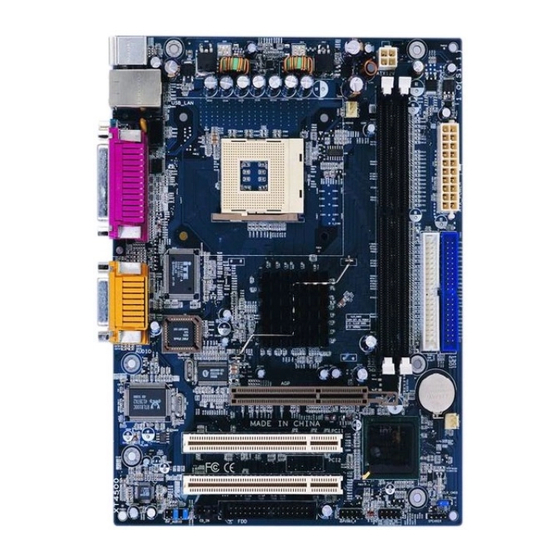
- Page 37 Board Layout of XT4500 Note: The layout includes all options. It is for your reference only.
- Page 38 Top :PS/2 Mouse Bttm:PS/2 Keyboard COM1 Top :LAN Bttm:USB1,2 Top :LAN Bttm:USB0,1 AUDIO North Bridge CPU_FAN DIMM1 South Bridge DIMM2 IDE2 ATX_POWER IDE1 PWR_FAN Note: pin1 for a jumpers are located on the side with black line. 1. PWR_LED 2. PWR_SW * EMPTY 3.
Need help?
Do you have a question about the XT4500 Series and is the answer not in the manual?
Questions and answers