E+E Elektronik EE310 Operation Manual
Humidity/temperature transmitter
Hide thumbs
Also See for EE310:
- Operating manual (36 pages) ,
- Operation manual (36 pages) ,
- User manual (48 pages)

Related Manuals for E+E Elektronik EE310


Summary of Contents for E+E Elektronik EE310
- Page 1 Operation manual EE310 Humidity/Temperature Transmitter BA_EE310_UL // V1.0 // Technical data subject to change // 194720...
- Page 2 E+E Elektronik® Ges.m.b.H. provides no warranty of any kind for this publication and accepts no liability for improper use of the products described. This publication might contain technical inaccuracies or typographical errors. The content is revised regularly and is not subject to change management. The manufacturer reserves the right to modify or change its described products at any time.
-
Page 3: Table Of Contents
RH / T adjustment and calibration ........................35 Scope of supply ............................36 Replacement parts / Accessories ......................36 Technical data ............................37 10 Appendix ..............................38 10.1 Appendix A ................................ 38 11 Ordering Guide ............................43 11.1 Measurand Code ............................... 43 Operating instructions for EE310 Humidity / Temperature Transmitter... -
Page 4: General
1.2.2. Alarm module with voltages >50 V (option AM2, AM6) The optional alarm module is isolated from the low-voltage side of EE310 by a special partition; this must remain fitted at all times in the bottom part of the enclosure. -
Page 5: Product Description
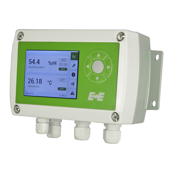
Product Description The UL certified EE310 is optimized for reliable indoor and outdoor measurement in demanding industrial applications. In addition to highly accurate measurement of relative humidity (RH) and temperature (T), the transmitter also calculates parameters such as dew point, absolute humidity and mixing ratio. -
Page 6: Models
Modular enclosure Don’t remove the mounting plate. Opening will void warranty! Models EE310 is available for wall, surface or duct mount as well as with various remote probes. The remote probes can be employed up to 180 °C and 20 bar (356 °F) -
Page 7: Installation
• Mount the two DIN rail brackets (to be ordered separately, see chapter 8 Replacement parts / Acces- sories) onto the back side of the enclosure. • Snap in the enclosure onto the DIN rail Fig. 5 DIN rail installation Operating instructions for EE310 Humidity / Temperature Transmitter... -
Page 8: Electrical Connection
Electrical connection The electrical installation of the EE310 shall be performed by qualified personnel only. Observe all applicable national and international requirements for the installation of electrical devices. Analogue outputs Both analogue outputs shall be configured to either voltage or current. Measurands, analogue range and scaling are freely selectable. - Page 9 Model Type Ratings Terminals RS485 A (=D+) (7) – 0-5V EE310 with option J3 Modbus RTU RS485 B (=D-) (8) – (SELV Limited Energy source) GND RS485 (6) Tab. 1 Electrical Connections Operating instructions for EE310 Humidity / Temperature Transmitter...
-
Page 10: Connection Diagram Option E4
3.2.2 Connection diagram Option E4 GND Output OUT 2 OUT 1 power supply + analogue output Fig. 8 Plug option E4 for EE310 (front connector view) GND RS485 (shielded) Model Supply Input Terminals n.c. RS485 A Voltage/Frequency (=D+) Indoor use:... -
Page 11: Connection Diagram Options E6 And E12
Fig. 10 Plug option E6 and E12 (front connector view) GND RS485 GND Output (shielded) OUT 2 n.c. n.c. RS485 A (=D+) OUT 1 n.c. n.c. RS485 B Operating instructions for EE310 Humidity / Temperature Transmitter (=D-) Modbus RTU Analogue output... -
Page 12: Connection Diagram Conduit Option
Note for E24: ½” Liquid-Tight Flexible Nonmetallic Conduit Type B (FNMC-B) is installed. Cable used for installation shall be suitable flexible listed cord/cable in accordance with NEC. Local regulation for installation must be observed. Operating instructions for EE310 Humidity / Temperature Transmitter... - Page 13 Terminals RS485 A (=D+) (7) – 0-5V EE310 with option J3 Modbus RTU RS485 B (=D-) (8) – (SELV Limited Energy source) GND RS485 (6) Tab. 7 Conduit options E23 / E24 Operating instructions for EE310 Humidity / Temperature Transmitter...
-
Page 14: Connection Diagram For Integrated Power Supply Module Am3
Power supply 100 - 240 V AC for polycarbonate enclosure Fig. 12 Plug option AM3 for EE310 (front connector view) External diameter of the supply cable for option AM3: 10-12 mm (0.39-0.47”) Maximum wire cross section for AM3 connecting cable: 1.5 mm²... -
Page 15: Connection Digram For Integrated Power Supply Module Am5
CANADA: 0.7 Nm 8 - 35 V DC Supply 12 - 30 V AC Analogue outputs OUT 1 OUT 2 GND RS485 Modbus RTU RS485 A (=D+) (galvanically isolated) RS485 B (=D-) Operating instructions for EE310 Humidity / Temperature Transmitter... -
Page 16: Connection Diagram For Alarm Outputs Am2
NO (1) EE310 with option AM2 Max. switch load: 250 Vac / 6 A and 28 Vdc / 6 A C (2) - Min. switch load: 12 Vacdc / 100 mA NC (3) Operating instructions for EE310 Humidity / Temperature Transmitter... - Page 17 (SELV Limited Energy source) Model Type Ratings Terminals RS485 A (=D+) (7) – EE310 with option AM3 0-5V Modbus RTU RS485 B (=D-) (8) – and J3 (SELV Limited Energy source) GND RS485 (6) Operating instructions for EE310 Humidity / Temperature Transmitter...
-
Page 18: Connection Diagram For Alarm Outputs Am6
Voltage/Frequency Indoor use: 12 to 30Vac, 50/60Hz (Class 2 supply) 8-35Vdc (LPS) V+ (1) – EE310 with option AM6 Outdoor use: GND (2) 12 to 16Vac, 50/60Hz (Class 2 supply) 8-35Vdc (LPS) Operating instructions for EE310 Humidity / Temperature Transmitter... -
Page 19: Probe Mounting
For mounting template of enclosure see chapter 3.1 Mechanical installation / Fig. 4 Dimensions and mounting template of polycarbonate enclosure in mm (inch). T working range probe: -40...+80 °C (-40...176 °F) electronics -40...+60 °C (-40...140 °F) -20...+50 °C (with display) (-4...122 °F) Operating instructions for EE310 Humidity / Temperature Transmitter... -
Page 20: T5: Remote Probe Up To 180 °C
For probe hanging onto its cable from the ceiling in applications where condensation is likely to happen it is important to avoid condense water getting from the cable to the probe and into the sensing head. For this use the drip water protection. Operating instructions for EE310 Humidity / Temperature Transmitter... -
Page 21: T10-T8: Remote Probe Up To 180 °C
EE310-T10 probe General safety instructions for installation The installation, commissioning and operation of the EE310-T10 may be performed by qualified staff only. Special attention shall be paid to the correct installation of the probe into the process. In case of inappropriate installation there is the risk for the probe to be suddenly expulsed due to the pressure in the process. -
Page 22: T10: Installation Of The Probe Directly In The Process With Sliding Fitting Up To 20 Bar (290 Psi)
±40 °C from the regular temperature during normal operation. (±72 °F) Replace the metal sealing ring (see Fig. 19 Installation of the EE310 probe directly into the process) by a new one every time before re-installing the probe. Probe installation steps •... -
Page 23: T10: Installation Of The Probe
Observe the correct positioning of the sealing element 1 before reinstalling the probe. Replacement of the sealing element In case of repeated installations and removals the sealing element 1 can might damaged. It can be replaced by the user. Operating instructions for EE310 Humidity / Temperature Transmitter... -
Page 24: T8 - T10: Installation Of The Probe With Cut-In Fitting Up To 100 Bar
Re-mounting: • Slide measurement sensor with clamping rings into the fitting as far as it will go. • Tighten the nut “fingertight”, then tighten by approx. a ¼ turn using a spanner. Operating instructions for EE310 Humidity / Temperature Transmitter... -
Page 25: Optional Modules
AM6 In accordance with NFPA 70, NEC and with CSA C22.1, CEC, Part 1. A switch or circuit-breaker must be included in the installation. It must be marked as disconnecting device for the EE310. Disconnecting means all current-carrying conductors shall be disconnected. Additional it must be suita- ble located and easily reached. - Page 26 Dew point [K] Hysteresis Frost point [K] Volume concentr. [ppm] Standard Normal state Inverted Standard Error indication Normal state Inverted * Menu only available with connected alarm module during EE310 start-up Operating instructions for EE310 Humidity / Temperature Transmitter...
-
Page 27: Integrated Power Supply 100
RS485 Module - Modbus RTU (option J3) Instructions for Modbus-Protocol-Setup please see Application Note AN0103 (www.epluse.com/EE310). Up to 32 EE310 transmitters with Modbus RTU interface can be connected in a RS-485 bus system. Slave n Slave 2 (max. 32) -
Page 28: Modbus Map
None Parity Even Stop bits value value Address * Menu only available with connected Modbus RTU module during EE310 start-up. Data transmission Factory settings Selectable values Baud rate 9600 300, 600, 1200, 2400, 4800, 9600, 19200, 38400, 57600, 76800 Data bits... -
Page 29: Operation
LED 4 Error LED power supply/ main board error LED on = error category 1 error LED flashes = error category 2 Fig. 30 Status LEDs are located at the USB port Operating instructions for EE310 Humidity / Temperature Transmitter... -
Page 30: Tft Colour Display (Optional)
3.5” TFT Colour Display (optional) The EE310 display includes a data logger and push buttons for full configuration of the device. Upon start-up of an EE310 with display, the data logger and the configuration menu will be initialised during the first 5 seconds. - Page 31 (first in first out memory). The last 20.000 logged values are available in the internal memory. The logged data can be downloaded with EE-PCS Product Configuration Software as .csv file by choosing the measurands and the time period. Operating instructions for EE310 Humidity / Temperature Transmitter...
-
Page 32: Configuration Menu
- language | date, time | parameters | password protection status and device information Status * Menu only available with connected corresponding modules. Status information The status information shows all actual EE310 settings. Fig. 33 Status information Buzzer ON / OFF Buzzer ON... -
Page 33: Maintenance
LED 1 (blue): analogue output is set to voltage. LED 2 (orange): analogue output is set to current. LED 3 (flashing green): supply voltage applied (microprocessor is active). LED 4 (red): constant lit: error category 1 flashes: error category 2 Operating instructions for EE310 Humidity / Temperature Transmitter... -
Page 34: Solving Typical Problems
• The filter cap shall be replaced once in a while with an E+E original one. A polluted filter cap causes longer response time of the device. • If needed, the sensing head can be cleaned. For cleaning instructions please see www.epluse.com/EE310. Operating instructions for EE310 Humidity / Temperature Transmitter... -
Page 35: Rh / T Adjustment And Calibration
(comparison with a reference) or adjustment (bringing the device in line with a reference). Calibration and adjustment at E+E Elektronik Calibration and/or adjustment can be performed in the E+E Elektronik calibration laboratory. For infor- mation on the E+E capabilities in ISO or accredited calibration please see www.eplusecal.com. -
Page 36: Scope Of Supply
Mating plug RKC 5/7 AM3 / E4 / E6 / E12 Mating plug RSC 5/7 (2 pcs. for option E12) E5 / E6 / E12 *) Other languages can be downloaded at www.epluse.com/EE310 Tab. 12 Scope of supply Replacement parts / Accessories see data sheet “Accessories”... -
Page 37: Technical Data
3) Appropriate for outdoor use, wet location, degree of pollution 2, overvoltage category II, altitude up to 3000 m (9843 ft). 4) IP65 not evaluated by UL. 5) Plastic enclosure, without M12 plug (E4, E5, E6, E12), conduit fitting E23, option D2, AM2, AM3 Operating instructions for EE310 Humidity / Temperature Transmitter... -
Page 38: 10 Appendix
IP settings* configuration of Ethernet Module Device settings settings - language | date, time | parameters | password protection Status status and device information * Menu only available with connected modules. Operating instructions for EE310 Humidity / Temperature Transmitter... - Page 39 Water activity [aw] Saturation [%] Water content [ppm] Limit high Alarm 1 value Wet bulb temp. [K] Dew point [K] Display alarm Frost point [K] Alarm 2 Limit low value Volume concentr. [ppm] Hysteresis Operating instructions for EE310 Humidity / Temperature Transmitter...
- Page 40 Reference value Offset Current measured value Reference Rel. humidity Reference value value value low 2 point adjustment Reference value Current measured Temperature high value Calibration status Reset to factory calibration Operating instructions for EE310 Humidity / Temperature Transmitter...
- Page 41 US units Capacity C76 Humidity coefficient Capacity offset Working pressure Capacity gain Parameters Probe replacement Resistance R0 Temperature coefficient TK Resistance Offset Password protection Activate Code Buzzer Status Status page Device info Operating instructions for EE310 Humidity / Temperature Transmitter...
- Page 42 Frost point [K] Volume concentr. [ppm] Standard Normal state Inverted Standard Error indication Normal state Inverted Modbus settings Baudrate value None Parity Even Stop bits value value Address Fig. 38 Configuration menu Operating instructions for EE310 Humidity / Temperature Transmitter...
-
Page 43: 11 Ordering Guide
°C wet bulb temperature Tw °C °F dew point Td °F mbar water vapour partial pressure e °C frost point Tf °F kJ/kg specific enthalpy h g/kg BTU/lb mixing ratio r gr/lb Operating instructions for EE310 Humidity / Temperature Transmitter... - Page 44 COMPANY HEADQUARTERS TECHNICAL OFFICES & PRODUCTION SITE E+E ELEKTRONIK Ges.m.b.H. E+E CHINA E+E ITALY www.epluse.com www.epluse.cn www.epluse.it Langwiesen 7 BEIJING Tel: +39 02 2707 8636 A-4209 Engerwitzdorf info@epluse.it Tel: +86 10 84992361 Austria info@epluse.cn Tel: +43 7235 605 0 SHANGHAI...
Need help?
Do you have a question about the EE310 and is the answer not in the manual?
Questions and answers