
Related Manuals for E+E Elektronik EE360


Summary of Contents for E+E Elektronik EE360
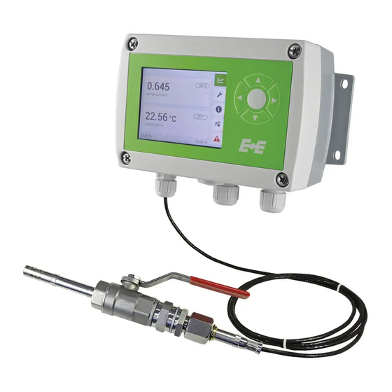
- Page 1 Operation manual EE360 Moisture in Oil Transmitter BA_EE360_e // V2.0 // Technical data subject to change // 194475...
- Page 2 E+E Elektronik Ges.m.b.H. accept warranty and liability claims neither upon this publication nor in case of improper treatment of the described products. The document may contain technical inaccuracies and typographical errors. The content will be revised and updated on aregular basis. The described products can be improved and changed at any time without prior notice.
-
Page 3: Table Of Contents
Solving typical problems ............................26 Sensor replacement ............................26 6.3. Cleaning.the.sensing.head./.filter.replacement ...................27 RH / T adjustment and calibration .......................27 technical data ............................29 Replacement parts / Accessories ....................30 Scope of supply ..........................30 10 Appendix ............................31 10.1 Appendix A ..............................31 Operating instructions for EE360 Moisture in Oil... -
Page 4: General
1.2.2. Alarm module with voltages >50V (option AM2) The optional alarm module is isolated from the low-voltage side of EE360 by a special partition; this must.remain.fitted.at.all.times.in.the.bottom.part.of.the.enclosure. The EE360 enclosure must be tightly closed during operation. An open enclosure corresponds to IP00 and exposes components carrying dangerous voltage. -
Page 5: Product Description
Product Description EE360 is dedicated for reliable monitoring of lubrication, hydraulic and insulation oils as well as diesel fuel. In addition to highly accurate measurement of water activity (aw) and temperature (T), EE360 cal- culates the absolute water content (x) in ppm (see also 2.3 Water activity vs. water content). -
Page 6: Probes
For assessing how far is the oil from saturation, x must be regarded together with EE360 calculates x out of the measured aw and T values. The calculation is oil dependent and re- quires.a.set.of.oil.specific.parameters..(Contact an E+E representative for details.) -
Page 7: Installation
•. Mount the two DIN rail brackets (to be ordered separately, see chapter 8 Replacement parts / Acces- sories) onto the back side of the enclosure. •. Snap in the enclosure onto the DIN rail Fig. 5 DIN rail installation Operating instructions for EE360 Moisture in Oil... -
Page 8: Mounting Of The Stainless Steel Enclosure
, not (0.2”) included in the scope of supply). Stainless steel enclosure (8.58“) (7.87“) (7.32“) (2.87“) (0.20“) (7.87“) (0.28“) (0.20“) Fig. 6 Dimensions and mounting template of stainless steel enclosure in mm (inch) Operating instructions for EE360 Moisture in Oil Transmitter... -
Page 9: Electrical Connection
3.2.2 Connection of the plug options Option E4 GND Output OUT 2 OUT 1 power supply + analogue output Option E5 GND RS485 (shielded) n.c. RS485 A (=D+) n.c. Operating instructions for EE360 Moisture in Oil RS485 B M16x1.5 (=D-) - Page 10 (AWG 16) External diameter of the cable for Modbus RTU and analogue output female plug: 4 - 6 mm (0.16 - 0.24”) Maximal wire cross section for connecting cable: 0.5 mm² (AWG 21) Operating instructions for EE360 Moisture in Oil Transmitter...
-
Page 11: Probe Mounting
±40 °C from the regular temperature during normal operation. (±72 °F) Replace the metal sealing ring (see Fig. 10 Installation of the EE360 probe directly into the process) by a new one every time before re-installing the probe. Probe installation steps •. -
Page 12: Installation Of The Probe With Ball Valve Set
(0.55”) stop valve stop valve Fig. 10 Installation of the EE360 probe directly into the process 3.3.2 Installation of the probe with ball valve set The ball valve set allows for installation and removal of the 200 mm probe without process inter- (7.87”) - Page 13 Observe the correct positioning of the sealing element 1 before reinstalling the probe. Replacement of the sealing element In case of repeated installations and removals the sealing element 1 can might damaged. It can be replaced by the user. Operating instructions for EE360 Moisture in Oil...
-
Page 14: Optional Modules
Example hysteresis mode % / RH Switching point 2 Hysteresis 2 Switching point 1 Hysteresis 1 open Terminal 1-2 / 4-5 closed open Terminal 2-3 / 5-6 closed Fig. 14 Example window mode Operating instructions for EE360 Moisture in Oil Transmitter... - Page 15 Switching point Mode Hysteresis Switch window Switching point Switching point high Hysteresis Standard Normal state Inverted Standard Error indication Normal state Inverted 1) Menu only available with connected alarm module during EE360 start-up Operating instructions for EE360 Moisture in Oil...
-
Page 16: Integrated Power Supply 100
National regulations for installation must be observed! RS485 Module - Modbus RtU (option J3) Instructions for Modbus-Protocol-Setup please see Application Note AN0103 (www.epluse.com/EE310). Up to 32 EE360 transmitters with Modbus RTU interface can be connected in a RS-485 bus system. Slave n Slave 2 (max. 32) -
Page 17: Ethernet Module - Modbus Tcp (Option J4)
None Parity Even Stop bits value value Address * Menu only available with connected Modbus RTU module during EE360 start-up. Data transmission Factory settings Selectable values Baud rate 9600 300, 600, 1200, 2400, 4800, 9600, 19200, 38400, 57600, 76800 Data bits... -
Page 18: Ipv4-Settings
Fig. 18 Ethernet Module - DHCP setting The.setup.of.the.Modbus.TCP.communication.can.be.performed.via.EE-PCS.Product.Config- uration Software or via display and push buttons. Modifying the IP-Address via EE-PCS or display is possible only when the DHCP jumper is con- figured.“Static”..Otherwise.the.IP-settings.are.read-only Operating instructions for EE360 Moisture in Oil Transmitter... -
Page 19: Retrofit.with.ethernet.module
Water content 32-bit float Write registers: function code 0x06 for 16-bit and 0x10 (decimal: 16) for 32-bit 0001 Slave-ID 16-bit integer 5001 1388 Air pressure mbar 32-bit float 1) Use for adjustment and calibration. Operating instructions for EE360 Moisture in Oil... -
Page 20: Pluggable Probe (Option Pc4)
EE360 transmitters are optionally available with pluggable sensing probe, which is attached to the EE360 enclosure by a push-pull plug. If the probe or the probe cable gets damaged it is possible to easily replace the probe without humidity and temperature adjustment. The replacement probe (see order information below) is supplied with a set of 7 individual parameters. -
Page 21: Operation
Status LEDs are located at the USB port 3.5” tFt Colour Display (optional) The.EE360.display.includes.a.data.logger.and.push.buttons.for.full.configuration.of.the.device.. Upon.start-up.of.an.EE360.with.display,.the.data.logger.and.the.configuration.menu.will.be.initialised. during.the.first.5.seconds.. Chart + data logger Configuration menu Status information Buzzer ON / OFF Error indication / information Display settings Fig. 22 Display with push buttons Operating instructions for EE360 Moisture in Oil... -
Page 22: Chart + Data Logger
Axis 1 Scale minimum value Water content [ppm] Rel. humidity [%] Temperature [°C] Temperature [°F] Scale maximum value Temperature [K] Measurand Axis 2 Scale minimum value Scale maximum value Delete saved values Operating instructions for EE360 Moisture in Oil Transmitter... - Page 23 Each point in the graph represents a logged value. The points are connected by a linear interpo- lation. One point The data logging continues even when the data memory is full; new data is stored while the oldest.data.is.deleted.(first.in.first.out.memory)..The.last.20.000.logged.values.are.available.in.the. internal memory. The.logged.data.can.be.downloaded.with.EE-PCS.Product.Configuration.Software.as..csv.file.by. choosing the measurands and the time period. Operating instructions for EE360 Moisture in Oil...
-
Page 24: Configuration.menu
- language | date, time | parameters | password protection Status status and device information * Menu only available with connected corresponding modules. Status information The status information shows all actual EE360 settings. Fig. 24 Status information Buzzer on / oFF Buzzer ON... -
Page 25: Maintenance
LED 1 (blue): analogue output is set to voltage. LED 2 (orange): analogue output is set to current. LED 3 (flashing green): supply voltage applied (microprocessor is active). LED 4 (red): constant lit: error category 1 flashes:.error.category.2 Operating instructions for EE360 Moisture in Oil... -
Page 26: Solving Typical Problems
Since the performance of the instrument after the sensor exchange depends on the overall accuracy of the adjustment procedure, it is strongly recommended to return the device to E+E for sensor replace- ment. Operating instructions for EE360 Moisture in Oil Transmitter... -
Page 27: Cleaning.the.sensing.head./.Filter.replacement
(comparison with a reference) or adjustment (bringing the device in line with a reference). Calibration and adjustment at E+E Elektronik Calibration and/or adjustment can be performed in the E+E Elektronik calibration laboratory. For infor- mation on the E+E capabilities in ISO or accredited calibration please see www.eplusecal.com. - Page 28 2 reference value 1 measurement value 1 Measured value reference point HIGH reference point LOW factory setting: 80 % RH factory setting: 30 % RH Fig. 29 2 point adjustment procedure Operating instructions for EE360 Moisture in Oil Transmitter...
-
Page 29: Technical Data
The accuracy was calculated in accordance with EA-4/02 and with regard to GUM (Guide to the Expression of Uncertainty in Measurement). 3) Appropriate for outdoor use, wet location, degree of pollution 2, overvoltage category II, altitude up to 3000 m (9843 ft). Operating instructions for EE360 Moisture in Oil... -
Page 30: Replacement Parts / Accessories
Mating plug RSC 5/7 (2 pcs. for option E12) E5 / E6 / E12 Mating plug HPP V4 RJ45 Cat 5 *) Other languages can be downloaded at www.epluse.com/EE360 Tab. 4 Scope of supply Operating instructions for EE360 Moisture in Oil Transmitter... -
Page 31: 10 Appendix
Water activity [aw] Axis 1 Scale minimum value Water content [ppm] Rel. humidity [%] Temperature [°C] Temperature [°F] Scale maximum value Temperature [K] Measurand Axis 2 Scale minimum value Scale maximum value Delete saved values Operating instructions for EE360 Moisture in Oil... - Page 32 Reference value Offset Current measured value Reference Rel. humidity Reference value value value low 2 point adjustment Reference value Current measured Temperature high value Calibration status Reset to factory calibration Operating instructions for EE360 Moisture in Oil Transmitter...
- Page 33 SI units Measuring system US units Capacity C76 Humidity coefficient Capacity offset Working pressure Capacity gain Parameters Probe replacement Resistance R0 Temperature coefficient.TK Resistance Offset Oil parameter Password protection Activate Code Buzzer Operating instructions for EE360 Moisture in Oil...
- Page 34 Switching point Switching point high Hysteresis Standard Normal state Inverted Standard Error indication Normal state Inverted Modbus settings Baudrate value None Parity Even Stop bits value value Address Fig. 30 Configuration menu Operating instructions for EE360 Moisture in Oil Transmitter...
- Page 35 Operating instructions for EE360 Moisture in Oil...
- Page 36 COMPANY HEADQUARTERS TECHNICAL OFFICES E+E ELEKTRONIK Ges.m.b.H. E+E CHINA www.epluse.com www.epluse.cn E+E ITALY Langwiesen 7 BEIJING www.epluse.it A-4209 Engerwitzdorf Tel: +86 10 84992361 Tel: +39 02 2707 8636 Austria info@epluse.cn info@epluse.it Tel: +43 7235 605 0 SHANGHAI Fax: +43 7235 605 8 Tel: +86 21 61176129 info@epluse.com...
Need help?
Do you have a question about the EE360 and is the answer not in the manual?
Questions and answers