Table of Contents

Related Manuals for E+E Elektronik EE36 Series


Summary of Contents for E+E Elektronik EE36 Series
- Page 1 Series EE36 Series EE36 TRANSMITTER FOR TRANSMITTER FOR MOISTURE CONTENT IN OIL MOISTURE CONTENT IN OIL MANUAL MANUAL Hardware and Software Hardware and Software BA_EE36_06_e // technical data are subject to change // 302294...
- Page 2 E+E Elektronik ® Ges.m.b.H. doesn't accept warranty and liability claims neither upon this publication nor in case of improper treatment of the described products. The document may contain technical inaccuracies and typographical errors. The content will be revised on a regular basis. These changes will be implemented in later versions.
-
Page 3: Table Of Contents
TABLE OF CONTENTS HARDWARE GENERAL 1.1 Symbol assertion 1.2 Safety instructions 1.3 Environmental information PRODUCT DESCRIPTION INSTALLATION 3.1 Installation of the housing 3.2 Installation of the probe 3.2.1 General Safety instructions for installation 3.2.2 Installation of the probe directly in the process 3.2.3 Installation of the probe by utilizing the ball valve set ELECTRICAL CONNECTIONS 4.1 Connection diagram... -
Page 4: General
Environmental aspects Equipment from E+E Elektronik ® is developed with due consideration to all resultant environmental issues. When you dispose the equipment you should avoid environmental pollution. -
Page 5: Product Description
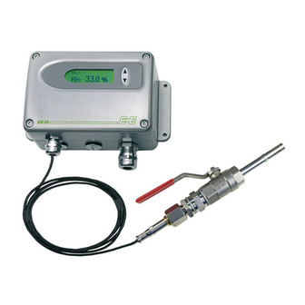
PRODUCT DESCRIPTION E+E Transmitter Series EE36 are specially designed for the measurement of water content in oil. The measured and the calculated values are available on two free scaleable and configurable analogue outputs. In addition, an optional relay output can be used for alarms and process control. -
Page 6: 3.2.2 Installation Of The Probe Directly In The Process
fixed installation 3.2.2 Installation of the probe directly in the process (pressure tight up For direct probe installation, a stop valve should be provided to 10bar (145psi) on both sides of the probe insert. This allows the sensor probe to be removed for maintenance and calibration without any problems. - Page 7 A too low torque results in a smaller tension force (fixing force) on the clamping sleeve. There is the risk of injury due to sudden expulsion of the sensing probe. A too high torque can lead to permanent deformation of the clamping sleeve and the sensing probe. This can make the removal and re-installation difficult or impossible.
-
Page 8: Electrical Connections
ELECTRICAL CONNECTIONS Connection diagram Alarm module connection diagram / Option Rel 1 Rel 2 Connection configuration of bottom part of the housing with plug connections / 8...35V DC; 12...30V AC (option C03/C07) Description: Connection assignment: Plug for supply and analogue output (front view) OUT1 OUT2... -
Page 9: Connection Configuration Of Bottom Part Of The Housing With Integrated Power Supply 100
Connection configuration of bottom part of the housing with integrated power supply / 100...240V AC (option V01) Description: Connection assignment: plug for RS232 and RxD / B- analogue output TxD / A+ (front view) OUT1 Euro-Standard OUT2 Description: Connection assignment: plug for 100-240V grounding metal housing... -
Page 10: Display Module / Option
Water content 4. MIN / MAX FUNCTION: Transmitters of the EE36 series can display the highest and lowest measured value measured since the last reset. Highest measured value: 1. Select the desired measurand. 2. To display the maximum value of the selected measurand, press the ∆ button for at least five seconds. -
Page 11: Alarm Module / Option
ALARM MODULE / OPTION The optional alarm module can be used for alarm and basic control functions. This module can be configured using the configuration software supplied. The user thus has the option of setting the measurand to be monitored (aw, x, T) and the threshold hysteresis for each relay. -
Page 12: Humidity/Temperature Calibration
HUMIDITY/TEMPERATURE CALIBRATION The EE36 transmitter series can be calibrated in two ways: 1-point humidity/temperature calibration: quick and simple calibration on a defined humidity/ temperature point (working point). 2-point humidity/temperature calibration: simple calibration for accurate measuring results over the whole humidity/temperature working range. •... -
Page 13: 2-Point Temperature Calibration
high calibration point: 6. Insert the sensor probe into the reference humidity 2 (high calibration point) and stabilise for at least 20 minutes. 7. BUTTON S2: Pressing the button for 5 seconds starts the procedure for the calibration mode RH. The calibration mode is indicated by the lit LED "D2"... - Page 14 2-point temperature calibration procedure on the circuit board: low calibration point: 1. Insert the sensor probe into the reference temperature 1 (low calibration point) and stabilise for at least 20 minutes. 2. BUTTON S1: Pressing the button for 5 seconds starts the procedure for the calibration mode temperature.
-
Page 15: 1-Point Humidity Calibration
1-point humidity calibration When the working range is limited to a certain more narrow range, a calibration at one humidity point is sufficient. • In accordance with the working range, either the high or low calibration point should be selected. (CP > or < 50% RH) •... -
Page 16: 1-Point Temperature Calibration
1-point temperature calibration When the working range is limited to a certain more narrow range, a calibration at one temperature point is sufficient. • In accordance with the working range, either the high or low calibration point should be selected. (CP ≥ or < 45 degC / 113°F •... -
Page 17: Resetting To Factory Calibration
Resetting the customer calibration to the factory calibration on the circuit board: 1. RH + T RESET: BUTTON S1 and S2: In neutral mode pressing buttons S1 and S2 simultaneously for 10 seconds customer calibration settings are reset to factory calibration. A short flash of the LED "D1"... -
Page 18: Maintenance
9) For further instructions, see Configuration software, chapter 5.3 "Sensor/Probe replacement" Sensor probe replacement / optional Transmitters of the EE36 series are available with an optional remote sensor probe that can be plugged into the middle section of the housing. If the sensor probe is damaged (damage to the cable, mechanical destruction of the sensor probe) it is possible to replace the probe. -
Page 19: Self-Diagnostics And Error Messages
Self diagnostics and error messages Self diagnostics via LEDs on the circuit board: • Green LED ⇒ flashing Supply voltage applied / Microprocessor is active • Red LED ⇒ constantly lit Humidity sensor element damaged ⇒ flashing Humidity sensor element accruing moisture (condensation!) Self diagnostics via display (where available): ⇒... -
Page 20: Technical Data
TECHNICAL DATA Measuring values Relative Humidity Water activity sensor HC1000-400 Measuring range 0...1a Accuracy incl. hysteresis and nonlinearity in air - Special calibration against certified standards ± 0.01a (0...0.9a ± 0.02a (0.9...1a - Standard calibration ± 0.02a (0...0.9a ± 0.03a (0.9...1a Temperature dependence of electronics typ. -
Page 21: Configuration Software
® impossibility of usage of a software product from E+E Elektronik and supportservices possibly associated with it or non-performance of support. -
Page 22: Icons On The Toolbar
ICONS ON THE TOOL BAR File Load: Loads a file with a saved transmitter configuration. Save: Saves the current transmitter configuration in a file. New Workspace: Opens a file for a new tree. Open Workspace: Opens existing trees. Save Workspace: Saves the current trees in an archive file. -
Page 23: Group
Group: Assigns a transmitter to a group. Network: This function is not available for the EE36 series. Interface: Selects the interface for connecting the transmitter to the network. (For information on how to set up a COM port, see Configuration Software, chapter 3.2 “Interfaces”). -
Page 24: Information
Deletes from the tree structure the selected transmitters, or the selected groups. Read: Reads and displays the configuration parameters of the selected transmitter. Read All: This function is not available for the EE36 series. Write: Writes the current configuration to the selected transmitter. Write All: This function is not available for the EE36 series. -
Page 25: Index - Index Cards
INDEX - INDEX CARDS Analogue For the configuration of both analogue outputs. Range: Using the drop-down input field, select either a standardized output signal (0-5V, 0-10V, 0-20mA, 4-20mA) or a user-defined current/voltage output range (upper and lower limits may be selected as required between the limits indicated). Physical Quantity: Selects the output physical quantities. -
Page 26: Sensor / Probe Replacement
Sensor / Probe Replacement In case of sensor or probe replacement, the characteristic values for this sensor/probe must be saved in the transmitter to ensure the transmitter will operate within the specified accuracy range. Replacement - Humidity Sensor: 1) Open the configuration of the selected transmitter by clicking on the button "Read Transmitter". -
Page 27: Calibration
Calibration Saturation content: Enter the parameter A and B for calculation of the water content x [ppm]. In addition to the manual calibration procedure on the circuit board (see Hardware, chapter 7. “Humidity/Temperature Calibration”), new calibrations can be performed using the EE36 software. Note: A 2-point calibration for temperature is only possible on the circuit board and is not supported by the software. - Page 28 2-point calibration Humidity: Calibration for accurate results over the entire measurement range. For calibration procedure, see Hardware, chapter 7. “Humidity/Temperature Calibration”. 1) Place the probe at the reference humidity (lower point). 2) Click on the Humidity 2-Point Calibration button. (In a separate window, the measured values will appear in both input fields) 3) Replace the value in the input field "Humidity Reading"...
-
Page 29: Information
Each transmitter is assigned a unique network address at the factory for precise identification. Note: This identification number is also issued for transmitters of the EE36 series, although transmitters of this series are not network compatible. Type: Name of the transmitter series. -
Page 30: Overview
OVERVIEW How to set-up a new transmitter? Menu "File" --> "New Workspace" Assign a name to the file and select the location to save the file Menu "Group" --> "New Group" Assign and add a name, then click on "Finish" Menu "... - Page 32 HEAD OFFICE: E+E ELEKTRONIK Ges.m.b.H. Langwiesen 7 A-4209 Engerwitzdorf Austria Tel: ++43/7235/605-0 Fax: ++43/7235/605-8 info@epluse.com TECHNICAL OFFICES: E+E CHINA B0820, Hui Bin Office Building, No. 8, Bei Chen Dong St., Chao Yang District, Beijing 100101, P.R. China Tel: ++86/10/84992361; ++86/10/84992362 Fax: ++86/10/84992363 info@epluse.cn...
Need help?
Do you have a question about the EE36 Series and is the answer not in the manual?
Questions and answers