
Subscribe to Our Youtube Channel
Related Manuals for E+E Elektronik EE31


Summary of Contents for E+E Elektronik EE31
- Page 1 Series EE31 HUMIDITY/TEMPERATURE TRANSMITTER MANUAL Hardware and Software BA_EE31_16_e // technical data are subject to change // 191678...
- Page 2 The content will be revised on a regular basis. These changes will be implemented in later versions. The described products can be improved and changed at any time without prior notice. © Copyright E+E Elektronik Ges.m.b.H. ® All rights reserved.
-
Page 3: Table Of Contents
TABLE OF CONTENTS HARDWARE GENERAL 1.1 Symbol assertion 1.2 Safety instructions 1.3 Environmental information PRODUCT DESCRIPTION INSTALLATION 3.1 Mounting Model A 3.2 Mounting Model B 3.3 Mounting Model D, Model H 3.4 Mounting Model E 3.5 Mounting Model F ELECTRICAL CONNECTIONS 4.1 Connection diagram 4.2 Connection diagram alarm module / Option 4.3 Connection configuration of bottom part of the housing with plug connections... -
Page 4: Hardware
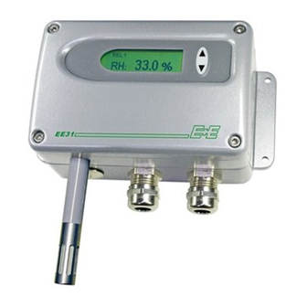
The modular housing enables a user-friendly operation and a fast replacement of the sensor unit for service purposes.By selecting a suitable housing version the EE31 series can be used for the entire range of humidity measurement applications: •... -
Page 5: Installation
(0.16”) Drilling with long hole: (5.8”) Mounting of model A (Wall mounting) For mounting template for metal and polycarbonate housing see above. Transmitters of the EE31-xAx series are designed for wall mounting. Working range: -40...60°C (-40...140°F) with display: -20...50°C (-4...122°F) -
Page 6: Mounting Model D, Model H
Mounting of model D, model H (Remote sensing probe) For mounting template for metal and polycarbonate housing see page 5. dimensions in mm (“) Transmitters of the EE31-xDx / EE31-xHx series are transmitters with remote sensing probes. Working range of sensor probe: model D: -40...180°C (-40...356°F) -
Page 7: Mounting Model F
(1.1”) (1.5”) polycarbonate housing: x = 20.5mm y = 25.4mm (0.8”) (1”) Transmitters of the EE31-xFx series are designed for wall mounting. Cable entry is from the rear side (e.g.: clean-room applications...). Working range: -40...60°C (-40...140°F) with display: -20...50°C (-4...122°F) -
Page 8: Electrical Connections
ELECTRICAL CONNECTIONS Connection diagram Alarm module connection diagram / Option Rel 1 Rel 2 Connection configuration of bottom part of the housing with plug connections / 8...35V DC; 12...30V AC (option C03/C06/C07/C08) Description: Connection assignment: Plug for supply and analogue output (front view) OUT1 OUT2... -
Page 9: Connection Configuration Of Bottom Part Of The Housing With Integrated Power Supply 100
Connection configuration of bottom part of the housing with integrated power supply / 100...240V AC (option V01) Description: Connection assignment: plug for RS232 and RxD / B- TxD / A+ analogue output (front view) OUT1 Euro-Standard OUT2 Description: Connection assignment: plug for 100-240V grounding metal housing... -
Page 10: Display Module / Option
°F Water vapour partial pres. mbar 4. MIN / MAX FUNCTION: Transmitters of the EE31 series can display the highest and lowest measured value measured since the last reset. Highest measured value: 1. Select the desired measurand. 2. To display the maximum value of the selected measurand, press the ∆ button for at RH: 63.0%... -
Page 11: Alarm Module (Optional)
5. MEASURED VALUES: The dominant value of the appropriate quantity is displayed in this field. For the factory configuration, the measured values may fall between the measurement ranges shown below. from up to units EE31-A,F EE31-B EE31-D,E Humidity % RH Temperature... -
Page 12: Humidity/Temperature Calibration
HUMIDITY/TEMPERATURE CALIBRATION The EE31 transmitter series can be calibrated in two ways. 1-point humidity/temperature calibration: quick and simple calibration on a defined humidity/temperature point (working point). 2-point humidity/temperature calibration: simple calibration for accurate measuring results over the whole humidity/temperature working range. -
Page 13: 2-Point Temperature Calibration
high calibration point: 6. Insert the sensor probe into the reference humidity 2 (high calibration point) and stabilise for at least 20 minutes. 7. BUTTON S2: Pressing the button for 5 seconds starts the procedure for the calibration mode RH. The calibration mode is indicated by the lit LED "D2"... - Page 14 2-point temperature calibration procedure on the circuit board! low calibration point: 1. Insert the sensor probe into the reference temperature 1 (low calibration point) and stabilise for at least 10 minutes. 2. BUTTON S1: Pressing the button for 5 seconds starts the procedure for the calibration mode temperature.
-
Page 15: 1-Point Humidity Calibration
1-point humidity calibration When the working range is limited to a certain more narrow range, a calibration at one humidity point is absolutely sufficient. • In accordance with the working range, either the high or low calibration point should be selected. (CP > or < 50% RH) •... -
Page 16: 1-Point Temperature Calibration
1-point temperature calibration on the circuit board When the working range is limited to a certain more narrow range, calibration temperature point absolutely sufficient. • In accordance with the working range, either the high or low calibration point should be selected. (CP ≥ or < 45 degC / 113°F •... -
Page 17: Resetting To Factory Calibration
Resetting the customer calibration to the factory calibration on the circuit board: 1. RH + T RESET: BUTTON S1 and S2: In neutral mode pressing both buttons simultaneously for 10 seconds customer calibration settings are reset to factory calibration. A short flash of the LED "D1" indicates the reset. 2. -
Page 18: Probe Replacement
Side Sensor probe replacement / optional Transmitters of the EE31-xDx and xEx series are available with an optional remote sensor probe that can be plugged into the middle section of the housing. If the sensor probe gets damaged (damage to the cable, mechanical destruction of the sensor probe) it is possible to replace the probe with re-adjustment. -
Page 19: Self-Diagnosis And Error Messages
Self diagnosis and error messages: Self diagnosis via LEDs on the circuit board: • Green LED ⇒ flashing Supply voltage applied / Microprocessor is active • Red LED ⇒ constantly lit Humidity sensor element damaged ⇒ flashing Humidity sensor element accruing moist (condensation!) Self diagnosis via display (where available): ⇒... -
Page 20: Network
NETWORK RS485 Network Up to 32 EE31 transmitters (additional "N" in order code) can be connected in a RS-485 bus system to a single PC interface. Using the software which is included in the scope of supply the transmitters can be configurated individually or in the entire network group. - Page 21 To adapt the RS232 interface on the PC to the RS485 network protocol, a signal converter (see schematic, page 19, point 2) is required. USB to RS232 converter: For connecting an EE31 transmitter to an USB- interface, following USB to R232 converter had been tested under MS Windows 2000 ®:...
-
Page 22: Ethernet-Module (Option)
Ethernet - Module (Option) An additional PCB, located in the bottom part of the housing, allows the EE31-series to be connected to a standardized 10/100 MBit-Ethernet network. The standardized interface allows to integrate the transmitters in a network. It is than possible to communicate from several remote workstations and the central administration with different transmitters. -
Page 23: Ethernet Connection
Com-Ports are possible! Communication with existing EE31 configuration-, data logging and visualization software: The created virtual Com-Ports can be addressed by the existing EE31 configuration-, data logging and visualization software, as long as the ComCenter software is running (active). 9.2.3.2 Installation of the ComCenter... - Page 24 Open ComCenter by either using the corresponding icon on the desktop or the path defined during the installation. Check the box "show End Devices only". In the list only EE31 transmitters (End Devices) within the network will be shown. Note: If the box "show End Devices only"...
- Page 25 (right bottom, next to the system time), but it remains active (running)! 9.2.3.5 Communication without ComCenter Transmitters with an Ethernet module can also be used straight without the ComCenter. Please contact E+E Elektronik if you need information regarding the EE31 protocol for Ethernet communication. Hardware...
-
Page 26: Replacement Parts / Accessories
HA010208 - Bracket for fixing onto mounting rails HA010203 - Drip water protection HA010503 - 1% calibration EE90/3H - Datalogging and analysis software (for EE31 only) HA010602 - RS485 Kit (HW + SW) for networking (for EE31 only) HA010601 Hardware... -
Page 27: Technical Data
TECHNICAL DATA: Technical Data EE31 Measurement values Relative humidity Humidity sensor HC1000-400 / HC105 Working range 0...100% RH Accuracy (including hysteresis, non-linearity and repeatability) -15...40°C ≤90% RH ± (1.3 + 0.3%*mv) % RH (5...104°F) -15...40°C >90% RH ± 2.3% RH (5...104°F) - Page 28 Technical Data for Options EE31 Display graphical LCD (128x32 pixels), with integrated push-buttons for selecting parameters and MIN/MAX function Integrated power supply 100...240V AC, 50/60Hz Alarm outputs 2 x 1 switch contact 250V AC / 6A 28V DC / 6A...
- Page 29 Hardware...
-
Page 30: Configuration Software
To remove the previous version, open the software folder in the system control panel. All of the programs installed on your system are located here. Uninstall the EE31 Configurator by clicking on the appropriate button and then install the upgrade. -
Page 31: Icons On The Tools Bar
ICONS ON THE TOOLS BAR File Load: Loads a file with a saved transmitter configuration. Save: Saves the current transmitter configuration in a file. New Workspace: Opens a file for a new tree (new network). Open Workspace: Opens existing trees (networks). Save Workspace: Saves the current trees (networks) in an archive file. -
Page 32: Group
(For information on how to set up a COM port, see Configuration Software, Chapter 3.2 Interfaces). Network address: Input of the network address for the EE31 transmitter for unique assignment within the network (see label on the transmitter housing). Name: Assigns a meaningful name coresponding to the transmitter. This name is displayed in the tree under the relevant group (e.g., Clean Room). -
Page 33: Information
"Write All." Warm Start: Resets and restarts the microprocessor of the selected transmitter. ? - Information Version: Displays the version number of the EE31 software currently installed and the contact information for E+E Elektronik. Configurations software... -
Page 34: Icon List
ICON LIST "Load File" (see Configuration Software, chapter 3.1 File) "Save File" (see Configuration Software, chapter 3.1 File) "New Transmitter" (see Configuration Software, chapter 3.4 Transmitter) "Read Transmitter" (see Configuration Software, chapter 3.4 Transmitter) "Save Transmitter" (see Configuration Software, chapter 3.4 Transmitter) "Read All Transmitters"... -
Page 35: Relay
Relay It is used to set both optional alarm outputs. Physical Quantity: Selects the physical quantity for each alarm output. Switching Point High: Sets the high switching point. Hysteresis: Sets the switching hysteresis that should be maintained each time the signal falls below the upper switching threshold. -
Page 36: Sensor / Probe Replacement
In addition to the manual calibration procedure on the circuit board (see Hardware, chapter 7 “Humidity/Temperature Calibration”), new calibrations can be performed using the EE31 software. Note: A two-point calibration for temperature is only possible on the circuit board and is not supported by the software. - Page 37 2-point calibration Humidity: Calibration for accurate results over the entire measurement range. For calibration procedure, see Hardware, chapter 7 “Humidity/Temperature Calibration”. 1) Place probe reference humidity (lower point). 2) Click on the Humidity Two-Point Calibration button. (In a separate window, the measured values will appear in both input fields) 3) Replace the value in the input field "Humidity Reading"...
-
Page 38: Information
Information Here you will find information of the selected transmitter. Network address: Each measuring transmitter is assigned a unique network address at the factory for precise identification within the network. Humidity Calibration Date: Provides information on the date of the last humidity calibration, but only where this was performed using the configuration software. -
Page 39: Overview
Menu " Transmitter" --> "New Transmitter" or Button "New Transmitter" Select the group for the transmitter using the pull-down menu "Group." If the transmitter is from the EE31 series and will belong to a transmitter network, then select the box "Network" and enter the network address assigned by E+E (can be found on the housing label) in the "Network Address"... - Page 40 HEAD OFFICE: E+E ELEKTRONIK Ges.m.b.H. Langwiesen 7 A-4209 Engerwitzdorf Austria Tel: +43 7235 605 0 Fax: +43 7235 605 8 info@epluse.com www.epluse.com TECHNICAL OFFICES: E+E CHINA / BEIJING Tel: +86 10 84992361 info@epluse.cn www.epluse.cn E+E CHINA / SHANGHAI Tel: +86 21 61176129 info@epluse.cn...
Need help?
Do you have a question about the EE31 and is the answer not in the manual?
Questions and answers