
Related Manuals for E+E Elektronik EE300E Series


Summary of Contents for E+E Elektronik EE300E Series
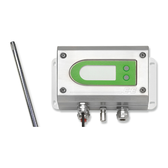
- Page 1 EE300Ex Series HUMIDITY / TEMPERATURE TRANSMITTER For Intrinsically Safe Applications Operating instructions BA_EE300EX_e // v1.7 / Technical data subject to change // 302484...
- Page 2 The company E+E Elektronik GmbH reserves the right to make modifications at any time and without prior notification, with no update requirement on models produced before the modifica- tion date.
-
Page 3: Table Of Contents
Contents GENERAL NOTES Explanation of symbols Safety instructions 1.2.1 General safety instructions Environmental aspects TECHNICAL DESCRIPTION General EE300Ex labeling Certification Housing and probe dimensions Humidity probe working range Dewpoint measurement in natural gas Measurement of moisture in oil INSTALLATION IN AN ExPLOSION HAzARD AREA General Housing assembly 3.2.1... -
Page 4: General Notes
• The devices are designed for operation on safety extra-low voltage (safety class III). Environmental aspects Products from E+E Elektronik® are developed incorporating all important environmental aspects. For this reason, avoiding environmental contamination should also be observed during disposal as well. -
Page 5: Technical Description
TECHNICAL DESCRIPTION General The entire EE300Ex transmitter can be installed directly in the explosion hazard area. The EE300Ex is the ideal transmitter in challenging industrial applications. The housing and measurement sensor made from stainless steel, as well as the proven E+E humidity sensors, ensure reliable and stable measurement results over long periods. -
Page 6: Ee300Ex Labeling
EE300Ex labeling Each EE300Ex is only characterized for one certificate. The Ordering Code on the Product label shows the type of the Ex Certificate on position “Ex-certificate”. The exact Ex marking with the certificate number is printed on the Hazardous label (Ex marking). EE300Ex with IECEx, USA or Canada labeling must not be installed in the European Union. -
Page 7: Housing And Probe Dimensions
Housing and probe dimensions wall mounting humidity and temperature - Model A (7“) (5.9“) (2.4“) L = filter cap Length in mm Stainless steel sinter filter 33 (1.3“) PTFE filter 33 (1.3“) Stainless steel grid filter 39 (1.5“) Oil filter 32 (1.26“) Remote sensing probe humidity/temperature up to 300 bar (4351 psi) - Model U Cable length acc. -
Page 8: Humidity Probe Working Range
wall mounting temperature - xT model (7“) (5.9“) (2.4“) Remote sensing probe temperature Cable length acc. to order code (6“) Single-sided screw connection 1/2" ISO or NPT Humidity probe working range The grey area shows the allowed measurement range for the humidity sensor. Although working points that lie outside of this range do not lead to the destruction of the element, the specified measurement accuracy cannot be guaranteed, however. -
Page 9: Installation In An Explosion Hazard Area
INSTALLATION IN AN ExPLOSION HAzARD AREA General The EE300Ex has been certified in accordance with the ATEX 94/9EC Directive, IECEX Scheme, , National Electrical Code (ANSI-NFPA 70 (NEC ) and © Canadian Electrical Code (CSA C22.1). Devices in explosion-hazard areas are only permitted for operation in atmospheric conditions -20 °C ≤ T ≤ 40 °C (-4°F) -
Page 10: Housing Assembly
Housing assembly The EE300Ex housing has a two-part construction. • Lower housing section with the connection and earthing terminals. • Upper housing section with the electronics and measurement probe. Upper housing part Lower housing part 3.2.1 Drilling plan for the housing (6.6") The lower housing section is mounted using 4 screws. -
Page 11: Assembly In Category 1 (Zone 0 / 20); Division
Assembly in category 1 (zone 0 / 20); Division 1 Only intrinsically safe power supply devices are approved to supply EE300Ex in category 1 or Division 1. In areas belonging to gas group IIC or Class I, Division 1, Group A,B, it must be ensured that during installation and operation, the possibility of impact and friction sparks has been excluded in rarely occurring fault situations. -
Page 12: Assembly In Categories 2 And 3 (Zone 1 2 / 21 22), Division
Assembly in categories 2 and 3 (zone 1 2 / 21 22), Division 2 Only intrinsically safe power supply devices and protective barriers are approved to supply EE300Ex in category 2 and 3 or Division 2. No display is permitted in the dust hazard area (Group III) or Class II, III. CH1 and CH2 must be galvanically isolated from one another during operation. -
Page 13: Mounting The Measurement Sensor
Mounting the measurement sensor To mount the transmitter, select a location with Wand / stable conditions, i.e. protected against direct Wall sunlight or rain. The measurement probe should be fitted at a location where represent- ative measured values are to be anticipated r >... -
Page 14: Mounting With Mounting Flange (Optional)
Installation instructions: • Tighten the union nuts finger-tight. • Mark the union nuts at the 6 o' clock position. • Hold the screw connection body tight and tighten the union nuts with 1 ¼ turns to the 9 'o clock position. Assembly with high pressure applications and applications with a high security factor: • Tighten the union nuts until the pipe can no longer be turned by hand or can no longer be moved axially in the fitting. -
Page 15: Mounting The Probe Using Ball Valve (Optional)
3.5.3 Mounting the probe using ball valve (optional) With ball valve mounting, the system being meas- ured does not need to be emptied or brought to a standstill to mount or remove the probe. Install the sensor head against the flow direction. Metal sealing ring (included with the ball Metal sealing ring... -
Page 16: Mounting The Probe Using Sensor Retraction Tool (Optional)
3.5.4 Mounting the probe using sensor retraction tool (optional) Observe the operating instructions of the sensor retraction tool! It may only be used the sensor retraction tool ZM-WA-025-040-EST or BG-WA-103-045-EST. With the sensor retraction tool 250 bar it may only be used the sensor probe model U. The delivery scope of the sensor probe includes the copper sealing for the Swagelok screw connection. -
Page 17: Calculation Of The Maximum Cable Length
Calculation of the maximum cable length Intrinsically safe power supply device STAHL 9160/13-11-11 (order code HA011405) Technical data for EE300Ex Supply voltage: = 9V + RL * 0.02A Max. current: max = 20mA Technical data for STAHL 9160/13-11-11 Nominal operating voltage: = 24V Input voltage for transmitter: = 16V... - Page 18 Technical data for connecting cable Cable type: ÖLFLEX® EB CY from manufacturer Lapp Kabel Cable cross-section: 4 x 0.75mm² (0.06x0.01in²) Operating capacity: 110nF/km Inductivity: 0.65mH/km Cable capacity for 300m CK = 0.3km * 110nF/km = 33nF (984ft) Cable inductivity for 300m LK = 0.3km * 0.65mH/km = 0.195mH (984ft) Technical data for EE300Ex (extract from the EC type approval test certificate)
-
Page 19: Electrical Connections
ELECTRICAL CONNECTIONS It is essential that installation, electrical connection, commissioning, operation and maintenance in explosion hazard areas are only carried out by trained specialist personnel authorised to do so by the system operator. Installation in accordance with NEC or CEC with consideration of the Control Drawing M1_1309080 For installation in an explosion hazard area, it is essential to ensure that all relevant standards are observed. -
Page 20: Terminal Assignment Ee300Ex
Terminal assignment EE300Ex Configuration adapter The digital interface is used only for device configuration and customer adjustment. The configurator software and the drivers are available for download free of charge from our website http://www.epluse.com/en/service-support/download-center/. The EE300Ex in combination with the configurator software is only permitted for use outside the hazard area. -
Page 21: Grounding And Potential Equalization
Grounding and potential equalization The EE300Ex must be integrated into the potential equalization to avoid hazards from electro- static charges. It shall apply the requirements of the standards EN60079-14, EN60079-25 or IEC60079-14, IEC60079-25. With a remote sensing probe, the probe should also be integrated with the screw connection with a maximum of 1 MΩ in the potential equalization. -
Page 22: Display (Optional)
DISPLAY (OPTIONAL) There is no display permitted in the gas hazard area for EPL Ga IIC or Class I, Division 1, Group A, B and in the dust hazard area for IIIA, IIIB and IIIC or Class II, III. Measured values Units Measured values selection top row 32.25°C... -
Page 23: Maintenance
MAINTENANCE It is essential that operation and maintenance in explosion hazard areas are only carried out by trained specialist personnel authorised to do so by the system operator. For maintenance and repair work in explosion hazard areas, the standards EN60079-17 or IEC60079-17, EN60079-19 or IEC60079-19 and the relevant national regulations must be applied. -
Page 24: Technical Data - Ee300Ex-Ht
TECHNICAL DATA - EE300Ex-HT Measuring values Relative humidity Humidity sensor HC1000 Measuring range 0...100% RH Accuracy (including hysteresis, non-linearity and repeatability, traceable to international standards, administrated by NIST, PTB, BEV...) -15...40°C ≤90% RH ± (1.3 + 0.3%*mv) % RH (5...104°F) -15...40°C >90% RH ±... -
Page 25: Technical Data - Ee300Ex-Xt
TECHNICAL DATA - EE300Ex-xT Measuring values Temperature Temperature sensor Pt1000 (Tolerance class A, DIN EN 60751) Measuring range sensor head wall mounting: -40...60°C (-40...140°F) remote sensing probe: -70...200°C (-94...392°F) ∆°C Accuracy ° C Temperature dependence of electronics typ. 0.005 °C/°C Outputs Scaleable analogue output 4 - 20 mA (2-wire) -
Page 26: Ec Declaration Of Conformity
EC DECLARATION OF CONFORMITY... -
Page 27: Iecex Certificate Of Conformity - Coc
IECEx CERTIFICATE OF CONFORMITY - COC...
Need help?
Do you have a question about the EE300E Series and is the answer not in the manual?
Questions and answers