E+E Elektronik EE310 Operation Manual
Humidity/temperature transmitter
Hide thumbs
Also See for EE310:
- Operating manual (36 pages) ,
- Operation manual (44 pages) ,
- User manual (48 pages)
Table of Contents
Advertisement
Quick Links
Download this manual
See also:
Operating Manual
Advertisement
Table of Contents

Related Manuals for E+E Elektronik EE310


Summary of Contents for E+E Elektronik EE310
- Page 1 Operation manual EE310 Humidity/Temperature Transmitter BA_EE310_e // V2.2 // Technical data subject to change // 194474...
-
Page 2: Fcc Notice
E+E Elektronik® Ges.m.b.H. provides no warranty of any kind for this publication and accepts no liability for improper use of the products described. This publication might contain technical inaccuracies or typographical errors. The content is revised regularly and is not subject to change management. The manufacturer reserves the right to modify or change its described products at any time. -
Page 3: Table Of Contents
Cleaning the sensing head / filter replacement ...................27 RH / T adjustment and calibration .......................27 Replacement parts / Accessories ....................28 Technical data ............................29 10 Appendix ............................30 10.1 Overview ..............................30 10.2 Detailed information ............................30 10.3 Optional menu ............................33 Operating instructions for EE310 Humidity / Temperature Transmitter... -
Page 4: General
1.2.2 Alarm module with voltages >50 V (option AM2) The optional alarm module is isolated from the low-voltage side of EE310 by a special partition; this must remain fitted at all times in the back section of the enclosure. The EE310 enclosure must be tightly closed during operation. An open enclosure corresponds to IP00 and exposes components carrying dangerous voltage. -
Page 5: Intended Use
Various models are available including wall, duct and remote probe. The remote probe can be used up to 180 °C (356 °F) and the pressure tight probe up to 20 bar (290 psi). The use of the EE310 other than described in this manual is not allowed. -
Page 6: Scope Of Supply
Additional cable gland / connector* Probe / cable gland / connector* * optional Connection terminal block RS485 add on chip Back section Space for optional modules Front section Mounting plate Fig. 2 Modular enclosure Operating instructions for EE310 Humidity / Temperature Transmitter... -
Page 7: Dimensions
T2: Duct mount (7.87“) (0.60“) (7.87“) 1/2“ ISO or 1/2“ NPT adjustable min. 23 / max. 164 (1“) (6.5“) 1) Refer to ordering guide 2) L = filter length; refer to data sheet "Accessories" Operating instructions for EE310 Humidity / Temperature Transmitter... -
Page 8: Installation
• Mount the two DIN rail brackets (to be ordered separately, see chapter 8) onto the back section. • Snap in the enclosure onto the DIN rail Fig. 5 DIN rail installation Operating instructions for EE310 Humidity / Temperature Transmitter... -
Page 9: Electrical Connection
EN 61140, class III (EU) and class 2 supply (North America). For EE310 with alarm module (option AM2) or integrated power supply 100...240 V AC (option AM3), the metal housing must be grounded during operation. -
Page 10: Electrical Connection And Wiring
4.2.1 Electrical connection and wiring EE310/EE360 - Electrical connection for stainless steel housing (HS2) Standard Standard Standard Option Polycarbonate enclosure Stainless steel enclosure Pin assignment Standard Standard Standard Option E4 Standard Cable glands OUT 1 OUT 2 OUT 1 OUT 1 Standard 2x M16x1.5... - Page 11 Option AM2 Inverted op Standard operation mode 2x M16x1.5 REL 2 REL 1 2x M16x1.5 REL 1 Inverted operation mode Standard operation mode Inverted operation mode Standard operation mode 2x M16x1.5 REL 1 Operating instructions for EE310 Humidity / Temperature Transmitter...
- Page 12 External diameter of the cable for Modbus RTU and analogue output female plug: 4 - 6 mm (0.16 - 0.24”) REL 2 Maximal wire cross section for connecting cable: 0.5 mm² (AWG 21) 2x M16x1.5 REL 1 Inverted operation mode Standard operation mode Operating instructions for EE310 Humidity / Temperature Transmitter...
-
Page 13: Probe Mounting (Wall / Duct Version)
For probe hanging onto its cable from the ceiling in applications where condensation is likely to happen it is important to avoid condense water getting from the cable to the probe and into the sensing head. For this use the drip water protection, see chapter 8. Operating instructions for EE310 Humidity / Temperature Transmitter... -
Page 14: Mounting Pressure Tight Probe Of Ee310-T10
Mounting pressure tight probe of EE310-T10 General safety instructions for installation The installation, commissioning and operation of the EE310-T10 may be performed by qualified staff only. Special attention shall be paid to the correct installation of the probe into the process. In case of inappropriate installation there is the risk for the probe to be suddenly expulsed due to the pressure in the process. - Page 15 • After the probe has been pushed out of the process up to the stop, close the ball valve. • Remove the probe from the ball valve. Observe the correct positioning of the sealing element 1 before reinstalling the probe. Operating instructions for EE310 Humidity / Temperature Transmitter...
-
Page 16: Optional Modules
Example hysteresis mode % / RH Switching point 2 Hysteresis 2 Switching point 1 Hysteresis 1 open Terminal 1-2 / 4-5 closed open Terminal 2-3 / 5-6 closed Fig. 14 Example window mode Operating instructions for EE310 Humidity / Temperature Transmitter... -
Page 17: Integrated Power Supply 100
/ inverted) can be set via EE-PCS Product Configuration Software or using the display and the push buttons (see chapter 10.3 / Fig. 35). Integrated power supply 100...240 V AC (option AM3) This module allows the EE310 to be powered with 100...240 V AC (50/60 Hz), 2 VA. polycarbonate stainless steel enclosure enclosure Fig. -
Page 18: Rs485 Module - Modbus Rtu (Option J3)
The unit identifier of the MBAP header is not used and can be any value from 0 to 255. HTTP-Webserver (Port 80) For a quick communication check enter the desired IP in a web browser and connect with the EE310 Ethernet Module’s Webserver. -
Page 19: Ipv4-Settings
Modifying the IP-Address via EE-PCS or display is possible only when the DHCP jumper is set to “Stat- ic”. Otherwise the IP-settings are read-only. Supported Ethernet standard: 802.3i/u/x and af;IPv6 is not supported Operating instructions for EE310 Humidity / Temperature Transmitter... -
Page 20: Retrofit With Ethernet Module
5.4.3 Retrofit with Ethernet Module The EE310 can be retrofitted with an Ethernet Module. Before retrofitting please make sure, that the EE310 firmware is updated to the latest version by using the Configuration Software EE-PCS. • Firmware for Transmitter: V 1.0.22 or higher •... -
Page 21: Pluggable Probe (Option Pc4)
EE310-T5 and EE310-T10 transmitters are optionally available with pluggable sensing probe, which is attached to the EE310 enclosure by a push-pull plug. If the probe or the probe cable gets damaged it is possible to easily replace the probe without humidity and temperature adjustment. The replacement probe (see order information below) is supplied with a set of 7 individual parameters. -
Page 22: Operation
Operation Configuration interface The EE310 is ready to use and does not require any configuration by the user. The factory setup of EE310 corresponds to the type number ordered. For ordering guide please see data sheet at www. epluse.com/EE310. If needed, the user can change the factory setup by using a micro USB cable and the EE-PCS, Product configuration Software. -
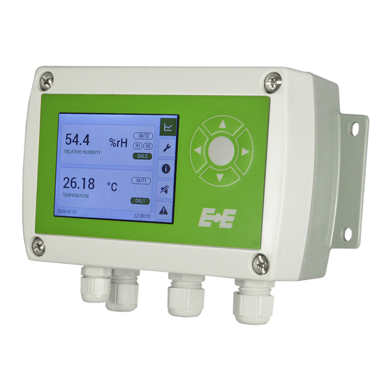
Page 23: 3.5" Tft Colour Display
3.5” TFT Colour Display The EE310 display includes a data logger and push buttons for full configuration of the device. Upon start-up of an EE310 with display, the data logger and the configuration menu will be initialised during the first 5 seconds. -
Page 24: Configuration Menu
IP settings* configuration of Ethernet Module Device settings settings - language | date, time | parameters | password protection status and device information Status * Menu only available with the corresponding optional modules. Operating instructions for EE310 Humidity / Temperature Transmitter... -
Page 25: Status Information
Status information The status information shows all actual EE310 settings. Fig. 24 Status information Buzzer ON / OFF Buzzer ON Buzzer OFF Error indication When an error occurs, the error indication shows the error code. Operating instructions for EE310 Humidity / Temperature Transmitter... -
Page 26: Maintenance
LED 1 (blue): analogue outputs one set to voltage. LED 2 (orange): analogue outputs one set to current. LED 3 (flashing green): supply voltage applied (microprocessor is active). LED 4 (red): constant lit: error category 1 flashes: error category 2 Operating instructions for EE310 Humidity / Temperature Transmitter... -
Page 27: Solving Typical Problems
(comparison with a reference) or adjustment (bringing the device in line with a reference). Calibration and adjustment at E+E Elektronik Calibration and/or adjustment can be performed in the E+E Elektronik calibration laboratory. For infor- mation on the E+E capabilities in ISO or accredited calibration please see www.eplusecal.com. Calibration and adjustment by the user Depending on the level of accuracy required, the humidity reference can be: •... -
Page 28: Replacement Parts / Accessories
„Humidity calibration kit“ 1) 2 pieces necessary per enclosure. 2) Only for devices with pluggable probe option PC4. For more details or illustrations refer also to data sheet “Accessories”. Operating instructions for EE310 Humidity / Temperature Transmitter... -
Page 29: Technical Data
Digital interface / protocol option J3 RS485 / Modbus RTU, max. 32 unit load devices on one bus (EE310 = 1 unit load; factory settings: 9600 bps, parity even, stop bit 1 / slave-ID 231) option J4 Ethernet-PoE with Modbus TCP... -
Page 30: 10 Appendix
Saturation [%] Axis 2 Scale minimum value Water content [ppm] Wet bulb temp. [K] Dew point [K] Scale maximum value Frost point [K] Volume concentr. [ppm] Delete saved values Fig. 29 Data-logging Operating instructions for EE310 Humidity / Temperature Transmitter... -
Page 31: Display Settings
Offset Current measured value Reference Rel. humidity Reference value value value low 2 point adjustment Reference value Current measured Temperature high value Calibration status Reset to factory calibration Fig. 32 Customer adjustment Operating instructions for EE310 Humidity / Temperature Transmitter... - Page 32 Working pressure Parameters Capacity gain Probe replacement Resistance R0 Temperature coefficient TK Resistance Offset Password protection Activate Code Buzzer ** changing the UTC time will delete measurment data! Fig. 33 Device settings Operating instructions for EE310 Humidity / Temperature Transmitter...
-
Page 33: 10.3 Optional Menu
Hysteresis Frost point [K] Volume concentr. [ppm] Standard Normal state Inverted Standard Error indication Normal state Inverted * Menu only available with connected alarm module during EE310 start-up Fig. 35 Alarm output Operating instructions for EE310 Humidity / Temperature Transmitter... - Page 34 Baudrate value None Parity Even Stop bits value value Address * Menu only available with connected Modbus RTU module during EE310 start-up. Fig. 36 Modbus settings Menu IP settings Type shows the status of the DHCP setting IP address value...
- Page 35 Operating instructions for EE310 Humidity / Temperature Transmitter...
- Page 36 COMPANY HEADQUARTERS TECHNICAL OFFICES E+E ELEKTRONIK Ges.m.b.H. E+E CHINA www.epluse.com www.epluse.cn E+E ITALY Langwiesen 7 BEIJING www.epluse.it A-4209 Engerwitzdorf Tel: +86 10 84992361 Tel: +39 02 2707 8636 Austria info@epluse.cn info@epluse.it Tel: +43 7235 605 0 SHANGHAI Fax: +43 7235 605 8 Tel: +86 21 61176129 info@epluse.com...
Need help?
Do you have a question about the EE310 and is the answer not in the manual?
Questions and answers