Table of Contents
Advertisement
Advertisement
Table of Contents

Related Manuals for Key-Disp KD21C


Summary of Contents for Key-Disp KD21C
-
Page 2: Table Of Contents
Contents Product name and model................................. 1 Specifications..................................... 1 Appearance and dimension..............................1 Function and button definition..............................2 ◆Function summary................................2 ◆Function area distribution..............................2 ◆Button definition................................. 2 Installation....................................3 General operations..................................3 ◆Switch E-bike system ON/OFF............................3 ◆Display interface.................................3 ◆Switch push-assistance mode ON/OFF......................... 4 ◆Switch lighting ON/OFF.............................. - Page 3 ◆Speed sensor information(optional)..........................13 ◆Throttle function information(optional)........................14 Throttle push assist enable/disable information......................14 Throttle level enable/disable information........................14 ◆System settings&information(optional)......................... 15 Battery power delay time settings..........................15 Push assist button enable/disable information......................16 Slow start up information............................... 16 ◆Power-on password settings............................17 Power-on password Enable/Disable..........................17 Power-on password change............................18 ◆Exit settings..................................
-
Page 4: Product Name And Model
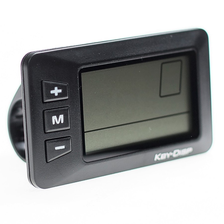
Product name and model E-bike Intelligent LCD Display Model: KD21C. Specifications ●24V/36V/48V Power Supply ●Rated working current: 10mA ●The maximum working current: 30mA ●Off-state leakage current: <1μA ●Working temperature:-20℃~ 60℃ ●Storage temperature: -30℃~ 70℃ Appearance and Size Product appearance and dimensional drawing (unit: mm) -
Page 5: Function And Button Definition
Function Summary and Button Definition ◆Function Summary KD21C has many functions to meet riders’ needs. The indication elements are as follows: ●Battery level ●Motor output power ●Assist level ●Speed indication (incl. current speed, Max. speed and Avg. speed) ●ODO and Trip ●Push-assistance function... -
Page 6: Installation
Installation KD21C can be mounted on the left side of handlebar close to its grip. Adjust the angle for a good screen view. Cut off the power before connecting the corresponding connectors between display and controller. General Operation ◆Switching the E-bike System mode ON/OFF To switch on the E-bike system and provide the power supply to the controller, hold the On/Off button for 2s. -
Page 7: Switch Push-Assistance Mode On/Off
Display indication cycle interface ◆Switching Push-assistance mode ON/OFF To activate the push-assistance function, press and hold the DOWN button. After 2 seconds, E-bike is activated to go at a uniform speed of 6 Km/h while the screen displays P”. “ The push-assistance function will be switched off as soon as you release the DOWN button. -
Page 8: Assist Level Selection
Switching Lighting on/off ◆Assist Level Selection The assist level of the E-bike drive can be changed anytime, even during riding. The assist level ranges from 0 to 5 (level 0 to level 5). The default assist level is “1” when the display is started. -
Page 9: Error Code Indication
Flash (low voltage) Battery Indicator ◆Error Code Indication The components of the E-bike system are continuously and automatically monitored. When an error is detected, the respective error code is indicated in text indication area. Refer to detailed definition of the error codes in Attached list 1. Error Code Indication ■Have the display inspected and repaired when an error code appears. -
Page 10: Backlight Brightness
Trip Distance Clearance Settings Interface ◆Backlight settings bL represents backlight settings. Level “1” is the lowest brightness. Level “2” is the medium brightness. Level “3” is the highest brightness. The default value is “1”. To change the backlight brightness, press the UP/DOWN button to increase or decrease until the desired brightness is displayed. -
Page 11: General Parameters Information
Mile and Kilometer toggling Settings Interface General Parameter Information To access general parameter information interface, hold both the UP and the DOWN button simultaneously for 2s to enter General Settings, then hold both the DOWN and ON/OFF button for 2s again to enter General Parameter Information. -
Page 12: Personalized Parameters Settings&Information
Personalized Parameter Settings&Information Personalized Parameter Settings&Information can meet a variety of riders’ personalized requirements. 8 options are Battery Power Bar Settings, Power assist level Settings, Over-current Cut Information, Power Assist Sensor Information, Speed Sensor Information, Throttle Function Information, System Settings&Information and Power-on Password Settings. Please refer to Attached list 2 for the definition of the symbols. -
Page 13: Battery Power Bar Settings
◆Battery Power Bar Settings VOL represents voltage settings. Each bar represents a voltage value. Each of the 5 values is to be entered one by one. For example, VOL 1 is the first bar voltage value, the default value is 31.5V. Press UP or DOWN button to increase or decrease the bar value and press ON/OFF button to store a changed setting and access the second bar. -
Page 14: Controller Over-Current Cut Information(Optional)
Hold the “ON/OFF” button for 2s to return to previous menu. Assist Level Ratio Interface ◆Controller Over-Current Cut Information CUR represents controller over-current cut information. . Press the ON/OFF button and then return to previous menu. Current Information Interface ◆Power Assist Sensor Information PAS represents power assist sensor information. -
Page 15: Pas Magnet Quantity Information
SCN represents PAS sensitivity settings. Press the ON/OFF button and then access magnet disk information. PAS sensitivity Information PAS Magnet Quantity Information N represents the number of magnets on PAS disk. Hold the ON/OFF button for 2s to return to previous menu. PAS Disk Magnet Quantity information ◆Speed Sensor Information SPS represents speed sensor information. -
Page 16: Throttle Level Enable/Disable Information
HL-N means throttle push-assistance function is disabled. HL-y means throttle push-assistance function is enabled. Throttle Push-assistance Enable/Disable Interface Throttle Level Enable/Disable Information HF-y means throttle speed is limited by current power assist level while HF-n means throttle speed is not limited by current power assist level. y means the maximum speed can only be the highest speed powered by current power assist level when you twist the throttle. -
Page 17: Battery Power Delay Time Settings
Press the UP/DOWN button to choose delay time 3s, 6s, 12s to change the settings. Press the ON/OFF button to confirm and access the max speed limit settings. Battery power delay time settings Interface Push-assistance Enable/Disable information PUS represents push-assistance enable/disable settings. “Y” means push-assistance is enabled, “N” means push-assistance is disabled. -
Page 18: Power-On Password Enable/Disable
the current password or default password’1212’. Press UP/DOWN button to increase or decrease the number and press i button to confirm digits one by one until the correct 4-digit password is completed. Press ON/OFF button to access power-on password Enable/Disable Settings. Password Input Interface Power-on Password Enable/Disable Press UP or DOWN button to choose Y or N and press ON/OFF button to confirm. -
Page 19: Exit Settings
Power-on Password Change Interface ◆Exit settings In Personalized Parameter Settings&Information Interface, Press the ON/OFF button is to confirm the input. Hold the ON/OFF button is to store the settings and exit the current setting. Hold the DOWN button is to cancel the operations but not to store setting data and return to previous menu. -
Page 20: Quality Assurance And Warranty Scope
Quality assurance and warranty scope Ⅰ Warranty 1) The warranty will be valid only for products used in normal usage and conditions. 2) The warranty is valid for 24 months after the shipment or delivery to the customer. Ⅱ Others The following cases do not belong to warranty scope: 1) The display is demolished. -
Page 21: Warnings
4. Make the display repaired when error code appears. ■ This manual instruction is a universal version for DISPLAY KD21C. Some versions of this display may be different from specification to specification as to the software. Please always refer to an actual version. -
Page 22: Attached List 3:Other Symbols
Attached list 2: Personalized Parameter settings Settings item Symbol Battery Power Bar Settings Power assistant level Settings Over-current Cut Information Power Assistant Sensor Information Speed Sensor Information Throttle Function Information System Settings and Information Power-on Password Settings Attached list 3:Other symbols Symbol Definition Trip distance clearance... - Page 23 Speed sensor Power delayed time Throttle-6km Throttle-PAS Button-6km Slowly start up Password Recover default...
Need help?
Do you have a question about the KD21C and is the answer not in the manual?
Questions and answers
How to reset total miles on display
The total miles (odometer) on the Key-Disp KD21C display cannot be reset. Only the trip counter can be reset by pressing and holding the plus (+) and minus (-) buttons, then selecting "Y" for yes, and confirming by holding the power button.
This answer is automatically generated
How to reset total mile on display
The total miles on the Key-Disp KD21C display cannot be reset. The trip counter can be reset by pressing and holding the plus (+) and minus (-) buttons, selecting "Y" for yes, and then holding the power button, but the total miles always remain on the bike.
This answer is automatically generated