Table of Contents
Advertisement
Quick Links
Advertisement
Table of Contents

Related Manuals for Key-Disp KD68C


Summary of Contents for Key-Disp KD68C
-
Page 2: Table Of Contents
Contents Product Name and model........................1 Specifications............................1 Appearance and Size........................1 Function Summary and Button Definition..................2 ◆Function Summary........................2 ◆Button Definition........................2 Install Instructions..........................2 General Operation...........................3 ◆Switching the E-bike System On/Off..................3 ◆Display Interface........................3 ◆Speed regulation........................3 ◆Assist Level Selection........................4 ◆Switching the Lighting On/Off....................4 ◆Power Indication........................4 ◆Error Code Indication.......................4 General Settings..........................5 ◆Trip Distance Clearance......................5... -
Page 3: Product Name And Model
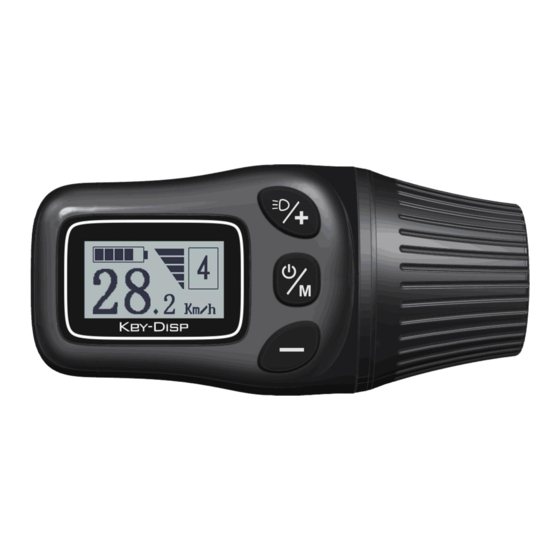
Product name and Model E-bike Intelligent LCD Display; Model: KD68C. Specifications ●24V/36V/48V Power Supply ●Rated working current: 10mA ●The maximum working current: 30mA ●Off-state leakage current: <1μA ●Working temperature:-20℃~ 60℃ ●Storage temperature: -30℃~ 70℃ Appearance and Size Product appearance and dimensional figure (unit: mm) -
Page 4: Function Summary And Button Definition
ON/OFF, UP, DOWN. Installation: KD68C can be mounted on the left side of handlebar close to its grip. Adjust the angle for a good display view. Cut off the power before connecting the corresponding connectors between display and controller.. -
Page 5: General Operation
Average Speed (Km/h) → Maximum Speed (Km/h) →Current Speed (Km/h).Each state displays for 3s, and then automatically returns to current speed. Display Interface ◆Speed regulation Turn speed handle of KD68C to adjust the speed of electric scooter (bicycle). Speed handle... -
Page 6: Assist Level Selection
◆Assist Level options Press the UP/DOWN to increase or decrease until the desired assistance level is displayed. The default power ranges from level “1” to level “3”. Level “1” is the minimum power. Level “3” is the maximum power. The default value is level “1”. Assist Level “3”... -
Page 7: General Settings
Error Code Indication ■The error code on the display needs to be removed. Or else you will not be able to ride the scooter(bike) normally. General Settings After the E-bike system is switched on, to access general settings menu, hold both UP and DOWN button for 2 s. -
Page 8: Unit Km/Mi Conversion
◆Unit Mile/KM Conversion Set Unit represents unit settings. To convert unit, press UP/DOWN to increase or decrease until the desired setting is displayed. To store a changed setting, press ON/OFF button to confirm and the display will show ' OK' and return to general settings interface . The default unit is Metric. Mile and Kilometer Conversion Settings Interface ◆Wheel Diameter Settings Set WD represents wheel diameter settings. -
Page 9: Battery Power Bar Settings
◆Battery Power bar Settings VOL represents battery voltage settings. Each bar represents a voltage value. 5 bars voltage values must be entered one by one. For example, VOL 1 is the first bar voltage value, the default value is 31.5V. To set battery power bar, press UP/DOWN to increase or decrease the value. -
Page 10: Power Assist Level Settings
◆Power Assistant Level Settings Power Assistant Level Mode option(*this function is not applicable to a scooter) Power Set represents power assist level settings. In assistance level settings, there are 8 modes for your options: 0-3, 1-3, 0-5, 1-5, 0-7, 1-7, 0-9, 1-9. The default mode is 1- To select the mode of power assist level, press UP/DOWN to increase or decrease the values until the desired mode is displayed. -
Page 11: Backlight Settings
To change basic settings, press the UP/DOWN button to increase or decrease the value of the current. To store a changed setting, hold the ON/OFF button and then return to personalized parameter settings interface. Current Set Interface ◆Backlight settings Backlight Set represents backlight settings. Level “1” is the low brightness. Level “2” is the medium brightness. -
Page 12: Power-On Password Enable/Disable
Power-on Password Input Interface Power-on Password Enable/Disable Press UP or DOWN button to choose Disable or Enable and press ON/OFF button to confirm. Power-on Password default is Disable. If you choose Enable, press ON/OFF button to enter Power-on Password Change interface, otherwise exit the power-on password settings interface. -
Page 13: Exit Settings
◆Exit settings In the settings interface, press ON/OFF button to confirm the input. Hold ON/OFF button more than 2 seconds to save the settings and then exit the current settings. Hold DOWN button more than 2 seconds to cancel current setting operation and exit the settings. -
Page 14: Connection Layout
Connection layout Connector wire sequence Display end connection wire end to display end Wire sequence table wire sequence Color Function Blue Yellow Green White Black Gray Purple ■Some products have wire connection with water-proof connectors, users can not see the color of wires in the harness. -
Page 15: Quality Assurance And Warranty Scope
Quality Assurance and Warranty Scope Ⅰ Warranty 1) The warranty will be valid only for products used in normal usage conditions. 2) The warranty is valid for 24 months after the shipment or delivery to the customer. Ⅱ The following cases do not belong to our warranty scope: 1) The display is demolished. - Page 16 Attached list 1:Error code definition Error Code Definition Current Abnormality Throttle Abnormality Motor Phase Abnormality Motor Hall Signal Abnormality Brake Abnormality Communication Abnormality Attached list 2:PAS ratio default value table Level level mode 0-3/1-3 — — — — — 0-5/ 1-5 —...
Need help?
Do you have a question about the KD68C and is the answer not in the manual?
Questions and answers