Table of Contents
Advertisement
Quick Links
Advertisement
Table of Contents

Related Manuals for Key-Disp KD51C-D


Summary of Contents for Key-Disp KD51C-D
-
Page 2: Product Model
Product model E-bike Intelligent LCD display Model: KD51C-D Specifications 24V/36V/48V Power Supply ● ● Rated working current :10mA The maximum working current: 30mA ● Off-state leakage current: <1μA ● ● Operating temperature: -20℃~ 60℃ Storage temperature: -30℃~ 70℃ ● Appearance and Size... -
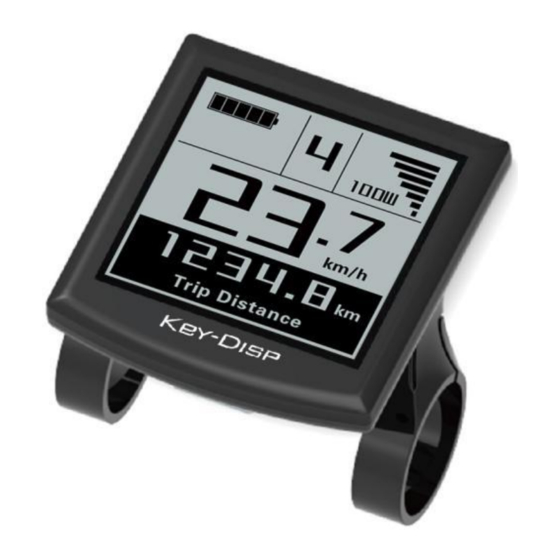
Page 3: Function Summary
Remote appearance and dimension drawing (unit: mm) Function Summary KD51C-D has many functions to meet your riding needs. The indicating contents are as follows: percentage ● Battery and battery indication Motor Power indication ● assist-level indication ● ● Speed indication (incl. running speed, Max. speed and Ave. speed) Odometer and trip distance ●... -
Page 4: General Operation
General Operation ◆Switching the E-bike System On/Off Briefly press the power button to switch on the E-bike system, and provides the power supply for the controller .To hold the power button for 2s, the E-bike system will be switched off .The E-bike system no longer use the battery power. When E-bike system is switched off, the leakage current is less than 1 μA. -
Page 5: Switching The Lighting On/Off
Push-assist Mode ■ Push-assist function may only be used while pushing the E-bike. Be aware of danger of injury when E-bike wheels do not have ground contact. ◆Switching the Lighting On/Off To switch on bike headlight, hold “ ” button for 2s. The display backlight brightness is automatically reduced. -
Page 6: Battery Indicator
Assist Level Change Interface ◆Battery Indicator The five battery bars represent the capacity of the battery. The five battery bars are bright when the battery is in high voltage. When the battery is in low voltage, battery frame will flash at the frequency of 1HZ to give a notice that the battery needs to be recharged immediately. -
Page 7: Error Code Indication
◆USB connection indication (optional) When a USB external device is inserted into display, the USB connection indication will be shown as follows: USB Connection Indication Interface ◆Error Code Indication The components of the E-bike system are continuously and automatically monitored. When an error is detected, the respective error code is indicated in text indication area. -
Page 8: Trip Distance Clearance
General settings interface ▉All the Settings are operated in the case of a parked bike ◆Trip Distance Clearance ‘Clear Trip’ represents trip distance clearance setting. To clear trip distance, press “+” button or “-” button to select the Yes or No. Yes represents clearing a single ride distance. -
Page 9: Wheel Diameter Settings
Mile and Kilometer Conversion Settings Interface ◆Wheel Diameter Settings ‘Wheel Diameter’ represents wheel diameter settings. To change basic settings, press the “+” or the “-” button to increase or decrease until the desired value is displayed. The default value is 26 inch. To store a changed setting, press the “i” button to confirm and "OK"... -
Page 10: Speed-Limit Settings
◆Speed-limit Settings The default value is 25Km/h. ‘Speed Limit’ represents the limited speed settings. When the current speed is faster than speed limit, the E-bike system will switch off automatically. Speed limit range is 12Km/h to 40Km/h. To change basic settings, press the “+” or the “-” button to increase or decrease until the desired value is displayed. - Page 11 Battery Power Bar Settings Interface Power Assist Level Settings ◆ 1. Assist-Level Mode Options ‘Set Power’ represents power assist level settings. There are 8 assist-level modes for your choice:0-3, 1-3, 0-5, 1-5, 0-7, 1-7, 0-9, 1-9. The default value is 0-5. To change the mode of assist-level, press the “+”...
-
Page 12: Controller Over-Current Cut Settings
2. PAS Ratio Settings To change the value of PAS ratio, press the "+" button or "-" button to choose the desired value, and then press the "i" button to confirm For example, the ratio range is “45-55 percent” for level “1”, ratio value can be changed and the default value is 50 percent. - Page 13 Current Settings Interface ◆Power Assist Sensor Settings ‘Assistant num’ represents PAS sensitivity settings. The sensitivity value is “5” to “24”. To store a changed setting, press the “i” button and then access the general settings. To change the sensitivity of PAS sensor, press “+” or “-” button to select sensitivity value.
-
Page 14: Backlight Contrast Settings
PAS Sensitivity Settings ◆Speed Sensor Settings (optional) ‘Speed Sensor’ represents speed sensor settings. The default value is 1 To change speed sensor settings, press the “+” or the “-” button to select the quantity of magnet head (the range is from 1 to 15). To store a changed setting, hold the “i”... -
Page 15: Power-On Password Settings
Backlight Brightness Settings Interface ◆Power-on Password Settings Password Settings on the screen means power-on password settings. The default password is 1212. To access the power-on password settings, press the“+”or the“-” button to modify the value and then press the “i” button to confirm digit one by one until the correct 4-digit password is completed, and then press the “i”... -
Page 16: Exit Settings
Set Password Interface ◆Power-on Password Change When the display shows Password Set,Enter Password 0000, to set new power-on password, press the “+” or the “-” button to modify the value and then press the “i” button to confirm digit one by one until the new 4-digit password is completed. To store the new power-on password, hold the “... -
Page 17: Quality Assurance And Warranty Scope
Quality Assurance and Warranty Scope Ⅰ Warranty (1)The warranty will be valid only for products used in normal usage conditions. ( 2 ) The warranty is valid for 24 months after the shipment or delivery to the customer. Ⅱ Others The following cases do not belong to our warranty scope. -
Page 18: Attached List 1:Error Code Definition
Warnings: 1. Use the display with caution. Don’t attempt to disconnect or link the connector when battery is on power. 2. Try to avoid hitting the display. 3. Don’t modify system parameters to avoid parameter disorder. 4. Make the display repaired when an error code appears. THIS MANUAL INSTRUCTION IS A GENERAL-PURPOSE VERSION.SOME ▉...
Need help?
Do you have a question about the KD51C-D and is the answer not in the manual?
Questions and answers