Table of Contents
Advertisement
Advertisement
Table of Contents

Related Manuals for Key-Disp KD21C


Summary of Contents for Key-Disp KD21C
-
Page 2: Table Of Contents
Content Product name and model ................1 Specifications ....................1 Appearance and Size ..................1 ◆Color categories ..................1 Function Summary and Button Definition ............1 ◆Function Summary ................1 ◆ Functional Area Distribution ..............2 ◆Button Definition .................. 2 General Operation .................. - Page 3 Assistance Level option ..............10 PAS Ratio Settings ................10 ◆Controller Over-Current Cut Settings ............ 11 ◆ Power Assistant Sensor Settings ............11 The Direction of PAS Settings ............11 The Sensitivity of PAS Settings ............11 Magnet quantity Settings ..............12 ◆...
-
Page 4: Product Name And Model
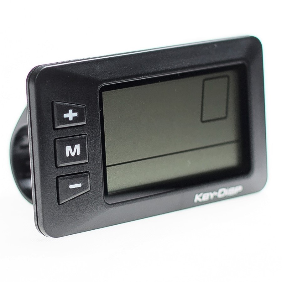
The cover of the display is two color options, black and white, and down shell of the display is only one black. Function Summary and Button Definition ◆Function Summary KD21C can provide a lot of functions to meet the users’ needs. The... -
Page 5: Functional Area Distribution
●Recover Default Settings Assembly The KD21C display should be mounted on the left handlebar of the Ebike at a comfortable angle. Cut off the power supply before connecting the display to the controller. ◆Functional Area Distribution ◆Button Definition... -
Page 6: General Operation
display that represented by the following functions respectively: MODE, UP, DOWN. General Operation ◆Switching the E-bike System On/Off To switch on the E-bike system, hold the MODE button for 2s. In the same way to hold the MODE button for 2s again, the E-bike system will be switched off. -
Page 7: Switching The Lighting On/Off
always, the E-bike will go on at a uniform speed of 6 Km/h, “P” is showed on the screen at the same time. The push-assistance function switches off as soon as you release the DOWN button. Push-assistance Mode ■ Push-assistance function may only be used when pushing the E- bike. -
Page 8: Battery Indicator
DOWN button, the interface shows “0” still and “0” flashing prompts low. To change assistance level, press the UP/DOWN to increase or decrease until the desired assistance level is displayed. Assistance Level “3” ◆Battery Indicator The five battery bars represent the capacity of the battery. When the battery is in low voltage, battery frame will flash to notice that the battery needs to be recharged immediately. -
Page 9: General Settings
Error Code Indication ■ When an error code appears, please refer to an authorized E-bike dealer . General Settings After the E-bike system is switched on, to access general settings menu, hold both the UP and DOWN button for 2s. ■... -
Page 10: Unit Km/Mi Conversion
To change the backlight brightness, press the UP/DOWN button to increase or decrease until the desired setting is displayed. To store a changed setting, press the MODE button and then access unit conversion settings. Backlight Brightness Settings Interface ◆Unit km/mi Conversion U represents unit settings, “1”... -
Page 11: Speed-Limit Settings
Ld represents wheel diameter settings. In general electable values are 16, 18, 20, 22, 24, 26, 700C and 28. The default value is 20 inch. To change basic settings, press the UP/DOWN button to increase or decrease until the desired value is displayed. To store a changed setting and access speed-limit settings interface, press the MODE button. -
Page 12: Battery Power Bar Settings
Assistant Sensor Settings, Speed Sensor Settings, Throttle Function Settings, System Settings and Power-on Password Settings. Please refer to the Attached list 2. To access Personalized Parameter Settings items option page, hold both the UP and DOWN button for 2s, then hold both the UP and DOWN button again. -
Page 13: Assistance Level Settings
◆Assistance Level Settings Assistance Level option In assistance level settings, there are 8 modes to select: 0-3, 1-3, 0- 5, 1-5, 0-7, 1-7, 0-9, 1-9. The default value is 0-5. To select the mode of assistance level, press the UP/DOWN button to increase or decrease until the desired setting is displayed. -
Page 14: Controller Over-Current Cut Settings
◆Controller Over-Current Cut Settings CUR represents controller over-current cut settings. CUR value can be changed from 7.0A to 22.0A. The default value is 15A. To change basic settings, press the UP/DOWN button to increase or decrease the value of the current. Hold the MODE button for 2s and then return to previous menu. -
Page 15: Magnet Quantity Settings
To change the sensitivity of PAS settings, press the UP/DOWN button to select sensitivity value. Briefly press the MODE button and then access magnet disk settings mode. The Sensitivity of PAS Settings Magnet quantity Settings N represents magnet numbers of PAS disk. The default value is 6. To change magnet numbers of PAS disk, press the UP/DOWN button to select quantity corresponding to PAS disk. -
Page 16: Throttle Definition
Speed Sensor Selection ◆Throttle Definition Throttle Push-assistance Enable/Disable HL represents throttle push-assistance function. HL-N represents throttle assistance push function is disabled. HL-y represents throttle assistance push function is enabled. The default value is N. To change throttle push-assistance function, press the UP/DOWN button to select Y or N. -
Page 17: System Settings
Throttle Level Enable or Disable Interface ◆System Settings Delay time settings of battery power DLY represents delay time of battery power settings. The default value is 3s. To change delay time settings, press the UP/DOWN button to select delay time 3s, 6s, 12s. Briefly press the MODE button to confirm and then access the max speed limited. -
Page 18: Button Push-Assistance Enable/Disable
Interface of Max Speed Limited Settings ■ This setting is the priority version. The speed is the maximum set by manufacturer. Button Push-assistance Enable/Disable PUS represents button push-assistance settings. Y represents button push is enabled, N represents button push-assistance is disabled. The default value is Y. -
Page 19: Slowly Start Up Settings
Interface of PAS Speed Settings Slowly Start up Settings SSP represents slowly start up. The range is “1-4”, “4” is the slowest. The default value is “1”. To change slowly start up settings, press the UP/DOWN button to select the desired value. Briefly press the MODE button and then circularly turn to Delay time settings of battery power page. -
Page 20: Power-On Password Enable/Disable
Power-on Password Entering Interface Power-on Password Enable/Disable To change power-on password enable/disable settings, press the UP/DOWN button to select Y or N. If it is Y, press the MODE button and then access power-on password modifying interface, otherwise exit the power-on password settings interface. -
Page 21: Exit Settings
Power-on Password Modifying Interface ◆Exit settings In the settings state, briefly press the MODE button is to confirm the input. Holding the MODE button is to store the settings, and then exit the current settings. Holding the DOWN button is to cancel the operating but not storing settings data, and then return to previous menu. -
Page 22: Quality Assurance And Warranty Scope
◆ Make the display repaired when error code appears. Quality assurance and warranty scope Ⅰ Warranty 1) The warranty will be valid only for products used in normal usage and conditions. 2) The warranty is valid for 24 months after the shipment or delivery to the customer. - Page 23 Line sequence table Line sequence Color Function Red(VCC) Blue(K) Lock Black(GND) Green(RX) Yellow(TX) ■ Some cable use the water-proof connector, users can not see the inside color. Attached list 1:Error code definition Error Code Definition Current Abnormality Throttle Abnormality Motor Abnormality Motor Hall Signal Abnormality Brake Abnormality Communication Abnormality...
- Page 24 Attached list 2: Personality Parameter settings Screen Settings item display Battery Power Bar Settings Power assistant level Settings Over-current Cut Settings Power Assistant Sensor Settings Speed Sensor Settings Throttle Function Settings System Settings Power-on Password Settings Attached list 3:Power assist table...
- Page 25 Attached list 4:symbol definition Symbol Definition Trip distance clearance Backlight Unit Voltage Wheel diameter Speed limit Controller over-current cut Backward Forward Sensitivity of PAS Speed sensor Power delayed time Throttle power assist walk Throttle-changing Button push Slowly start up Password Recover default...
Need help?
Do you have a question about the KD21C and is the answer not in the manual?
Questions and answers
what does error code 25 mean
On ebike display KD21 C max power assist diplays AO