Table of Contents
Advertisement
Quick Links
Advertisement
Table of Contents

Related Manuals for Key-Disp KD21C


Summary of Contents for Key-Disp KD21C
-
Page 2: Table Of Contents
Contents Product name and model ......................1 Appearance and Size ....................... 1 ◆Materials and Color ......................... 1 Function Summary and Button Definition ................. 2 ◆Function Summary ......................... 2 ◆Functional Area Distribution ....................2 ◆Button Definition ........................2 General Operation ........................2 ◆Power On/Off .......................... - Page 3 Throttle Assistance Push Enable or Disable ..............10 Throttle Level Enable or Disable ..................10 ◆System Settings ........................10 Delay time settings of battery power .................. 10 Max speed limited ........................11 Button PAS Settings ........................ 11 PAS Speed Settings ......................... 11 Slowly Start up Settings ......................
-
Page 4: Product Name And Model
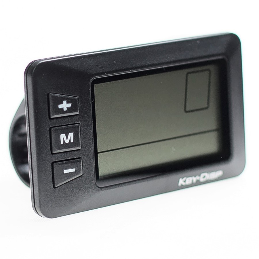
Appearance and Size ◆ Materials and Color KD21C product’s shell and hook are made of ABS and Nylon respectively. LCD transparent window lens is high hardness acrylic. Between -20℃ and 60℃ temperature, the mechanical performances of the shell materials are excellent, which ensure the usability of the shell. -
Page 5: Function Summary And Button Definition
Function Summary and Button Definition ◆ Function Summary KD21C can provide a lot of functions to fit the users’ need. The indicating contents are as following. ● Battery Indicator ● Motor Power Ratio ● Power assist level adjustment Indicator ●... -
Page 6: Display Interface
◆ Display Interface After starting up the display, default show is running speed and Total Distance . Press MODE to change the indicated information in sequence as below: Running Speed (Km/h) → Trip Distance (km) → Total Distance (km) → Travel Time(Hour.) →Max Speed (Km/h) →... -
Page 7: Pas Level Selection
Turn On/Off Backlight ◆ PAS Level Selection Press UP or DOWN to change the output power of the motor. The default power ranges from level 0 to level 5. The output power is 0 on Level 0. Level 1 is the minimum power. Level 5 is the maximum power. -
Page 8: Trip Distance Clearance
Hold MODE button to start the display, then hold both UP and DOWN for 2 seconds to enter general settings menu. ■ All the Settings are operated in the case of zero speed ◆ Trip Distance Clearance TC means single trip distance clearance settings, Press UP or DOWN to choose Y or N to clear trip distance. -
Page 9: General Parameter Settings
Inch and Metric Conversion Settings Interface General Parameter Settings Hold both UP and DOWN for 2 seconds to enter User settings. Then hold both DOWN and MODE more than 2 seconds is to enter w heel diameter Settings interface. ◆ Wheel Diameter Settings Ld means wheel diameter settings. -
Page 10: Battery Power Bar Settings
Hold both UP and DOWN more than 2 seconds to enter general settings, then hold both UP and DOWN again to enter personalized parameter settings items selection page. Press UP or DOWN to choose the personalized parameter settings items, and press MODE to enter the corresponding settings page. -
Page 11: Pas Ratio Settings
1-5 flash PAS Mode Select Interface PAS Ratio settings To modify the value of PAS ratio can match the different requirements. For example, the range is “45-55 percent” of 1 level, bottom value can be modified, and the default is 50 percent. Press MODE to confirm and turn to the next PAS ratio settings. After all PAS ratio inputted, hold MODE to confirm and return to previous menu, please refer to Attached list 3. -
Page 12: The Sensitivity Of Pas Settings
confirm and enter settings mode of PAS sensitivity, the default direction is“run-F”. Direction of PAS Sensor Settings The Sensitivity of PAS Settings SCN means the sensitivity of PAS settings. The sensitivity value is 2 to 9. 2 is the strongest, 9 is the weakest. Press UP or DOWN to select sensitivity value, and press MODE to confirm selection and enter magnet disk settings mode.The sensitivity of PAS default value is 2. -
Page 13: Throttle Definition
Speed Sensor Selection ◆ Throttle Definition Throttle Assistance Push Enable or Disable HL means throttle assistance push. HL-N means throttle assistance push function is disabled. HL-Y means throttle assistance push function is enabled. Press UP or DOWN to select Y, and press MODE to confirm the selection. Otherwise select N to enter Throttle Level Enable Settings, HL default value is N. -
Page 14: Max Speed Limited
Delay time of battery power interface Max speed limited MAX SPD means max speed limited settings. Press UP or DOWN to Set the max speed from 25Km/h~40 Km/h. Press MODE to confirm and enter Button PAS Settings. The default is 40Km/h. Interface of max speed limited settings ■... -
Page 15: Slowly Start Up Settings
Interface of PAS speed settings Slowly Start up Settings SSP means slowly start up. The range is 1-4, 4 is the slowest. Press UP or DOWN to choose, press MODE to confirm and turn to Delay time settings of battery power page. Hold MODE to confirm and return to previous menu. -
Page 16: Power-On Password Modify
Interface Power-on Password Disable Power-on Password Modify When the display shows P3, 0000, press MODE to choose digit one by one, press UP or DOWN to input the new password, then hold MODE to confirm the modification and exit settings. Restarting display will show P1,0000, input the new password to power on. Interface Power-on Password Modify ◆... -
Page 17: Operation Cautions
Operation Cautions Be care of the safety use. Don’t attempt to release the connector when battery is on power. ◆ Try to avoid hitting. ◆ Don’t split the waterproof sticker avoid affecting the waterproof performance. ◆ Don’t modify system parameters to avoid parameters disorder. ◆... - Page 18 Line sequence table Line Color Function Red(VCC) Blue(K) Lock Black(GND) Green(RX) Yellow(TX) ■ Some wire use the water-proof connector, users can not see the inside color. Attached list 1:Error code definition Error Code Definition Current Abnormality Throttle Abnormality Motor Abnormality Motor Hall Signal Abnormality Brake Abnormality Communication Abnormality...
- Page 19 Attached list 3:Power assist table Attached list 4:symbol definition Symbol Definition Trip distance clearance Backlight Unit Voltage Wheel diameter Speed limit Controller over-current cut Backward Forward Sensitivity of PAS Speed sensor Power delayed time Throttle power assist walk Throttle-changing Button push...
- Page 20 Slowly start up Password Recover default...
Need help?
Do you have a question about the KD21C and is the answer not in the manual?
Questions and answers
How to reset total miles on display
The total miles (odometer) on the Key-Disp KD21C display cannot be reset. Only the trip counter can be reset by pressing and holding the plus (+) and minus (-) buttons, then selecting "Y" for yes, and confirming with the power button.
This answer is automatically generated