Table of Contents
Advertisement
Advertisement
Table of Contents

Subscribe to Our Youtube Channel
Related Manuals for Key-Disp KD51C-U


Summary of Contents for Key-Disp KD51C-U
-
Page 2: Table Of Contents
Content Product Name and Model......................1 Specifications..........................1 Appearance and Size ........................1 Function Summary ........................2 ◆Function Summary....................... 2 ◆Functional Area Distribution....................3 General Operation ........................3 ◆Switching the E-bike System On/Off................3 ◆Display Interface........................3 ◆Switching Push-assistance Mode On/Off................4 ◆Switching the Lighting On/Off....................4 ◆Assistance Level Selection.................... - Page 3 The Direction of PAS Settings..................10 The Sensitivity of PAS Settings..................10 Magnet Quantity Settings....................11 ◆Speed Sensor (optional)....................11 ◆Throttle Definition (optional).................... 11 Throttle Push-assistance Enable/Disable..............11 Throttle Level Enable/Disable..................12 ◆System Settings (optional)....................12 Delay Time Settings of Battery Power................12 Max Speed Limited......................12 Button Push-assistance Enable/Disable................13 PAS Speed Settings......................13 Slowly Start Up Settings....................13...
-
Page 4: Product Name And Model
Product Name and Model Intelligent LCD display of E-bike; model: KD51C-U. Specifications ●24V/36V/48V Power Supply ●Rated working current: 10mA ●The maximum working current: 30mA ●Off leakage current: <1uA ●The supply controller working current: 50mA ●Working temperature: -20℃~ 60℃ ●Storage temperature: -30℃~ 70℃... -
Page 5: Function Summary
Function Summary ◆Function Summary KD51C-U can provide a lot of functions to fit the users’ needs. The indicating contents are as following: ●Smart battery indicator ●Motor-output indicator ●Assistance-level indication ●Speed indication (incl. running speed, max speed and average speed) ●Odometer and trip distance ●The push-assistance function... -
Page 6: Functional Area Distribution
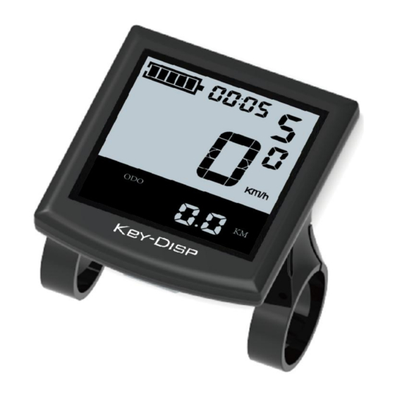
Functional Area Distribution ◆ Time Indication Battery Indicator Push-assistance Level Indication area USB Connection Indicator Power Indicator The Lighting Indicator Speed Indication Speed Unit Function List Range /Time Unit Text Indication Functional Area Distribution General Operation Switching the E-bike System On/Off ◆... -
Page 7: Switching Push-Assistance Mode On/Off
Switching Push-assistance Mode On/Off ◆ To activate the push-assistance function, hold the “-” button always. The E-bike’s drive is activated at a uniform speed of 6 Km/h. The push-assistance function is switched off as soon as you release the “walk” button on the operating unit. -
Page 8: Time Indication
Time Indication ◆ The time can be displayed in the 24 hour format. Time Indication Battery Indicator ◆ The five battery bars represent the capacity of the battery. Each bar of the battery pack symbol is equivalent to a capacity of approx. 20%. When the battery is in low voltage, battery frame will flash to notice that the battery needs to be recharged immediately. -
Page 9: Error Code Indication
Error Code Indication ◆ The components of the E-bike system are continuously and automatically monitored. When an error is detected, the respective error code is indicated in text indication area. Here is the detail message of the error code in Attached list 1 . Error Code Indication ■... -
Page 10: Unit Km/Mi Conversion
Unit km/mi Conversion ◆ U represents unit settings, “1” is mile and “2” is kilometer. The default value is “2”. To convert unit, press the “+” button or the “-” button to choose the desired setting item, and then press the “i” button to confirm. To store a changed setting, press the “i”... -
Page 11: Speed-Limit Settings
Wheel Diameter Settings Interface Speed-limit Settings ◆ LS represents the limit speed settings. When the current speed is faster than speed limit, the E-bike system will switch off automatically. Speed limit range is 12Km/h to 40Km/h. The default value is 25Km/h. To change basic settings, press the “+”... -
Page 12: Battery Power Bar Settings
Battery Power Bar Settings ◆ VOL represents voltage settings. Each bar represents a voltage value. 5 bars voltage values must be entered one by one. For example, VOL 1 is first bar voltage value. The default value is 31.5V. To set battery power bar, press the “+” or the “-” button to increase or decrease the number. -
Page 13: Controller Over-Current Cut Settings (Optional)
PAS Ratio Interface Controller Over-current Cut Settings (optional) ◆ CUR represents controller over-current cut settings. CUR value can be changed from 7.0A to 25.0A. The default value is 15A. To change basic settings, press the “+” or the “-” button to increase or decrease the value of the current. -
Page 14: Magnet Quantity Settings
The Sensitivity of PAS Settings Magnet Quantity Settings n represents magnet numbers of PAS disk. The default value is 6. To change magnet numbers of PAS disk, press the “+” or the “-” button to select quantity corresponding to PAS disk. To store a changed setting, hold the “i”... -
Page 15: Throttle Level Enable/Disable
Throttle Enable/Disable Interface Throttle Level Enable/Disable HF-y represents throttle level enabled, HF-N represents throttle level is disabled. The default value is N. To change throttle level function, press the “+” or the “-” button to select Y or N and then press the “i”... -
Page 16: Button Push-Assistance Enable/Disable
Interface of Max Speed Limited Settings ■ This setting is the priority version. The speed is the maximum set by manufacturer. Button Push-assistance Enable/Disable PUS represents button push-assistance settings. Y represents button push is enabled, N represents button push is disabled. The default value is Y. To change button push-assistance settings, press the “+”... -
Page 17: Power-On Password Settings
Interface of Slowly Settings Up Power-on Password Settings ◆ P2, 0000 on the screen means power-on password settings. The password is 1212. To access the power-on password settings, press the “+” or the “-” button to modify the value and then press the “i” button to confirm digit one by one until the correct 4-digit password is completed, and then press the “i”... -
Page 18: Exit Settings
Power-on Password Modify Interface Exit Settings ◆ In the settings state, press the “i” button is to confirm the input. Hold the “i” button is to store the settings, and then exit the current settings. Hold the “-” button is to cancel the operating but not storing settings data, and then return to previous menu. -
Page 19: Connection Layout
Connection Layout Connector line sequence Display-side Connector Display-side adapter Switch wiring Line sequence table Line Color Function Red(VCC) Blue(K) Lock Black(GND) Green(RX) Yellow(TX) ■ Some wire use the water-proof connector, users can not see the inside color. Operation Cautions Be careful of safe use. Don’t attempt to release the connector when battery is on power. - Page 20 Attached list 2:Power assist table Level Level selection 0-3/1-3 — — — — — — 0-5/ 1-5 — — — — 0-7/ 1-7 — — 0-9/ 1-9...
Need help?
Do you have a question about the KD51C-U and is the answer not in the manual?
Questions and answers