Table of Contents
Advertisement
Advertisement
Table of Contents

Related Manuals for Key-Disp KD58C


Summary of Contents for Key-Disp KD58C
-
Page 2: Table Of Contents
Contents Product name and model ....................... 1 Specifications ........................... 1 Appearance and Size ......................1 Function Summary and Button Definition ................2 ◆Function Summary ......................2 ◆Button Definition .......................2 Installation..........................2 Function Area Distribution ......................2 General Operation ........................2 ◆Switching the E-bike System On/Off................2 ◆Display Interface......................2 ◆Switching Push-assist mode On/Off................ - Page 3 ◆Power-on Password Settings..................10 Power-on Password Enable/Disable................. 10 Power-on Password Modify..................10 ◆Exit settings........................10 Recover default settings....................... 11 Quality assurance and warranty scope................11 Connection layout........................12 Warnings..........................12 Attached list 1 Error code definition..................13 Attached list 2 PAS ratio default value table..............13...
-
Page 4: Product Name And Model
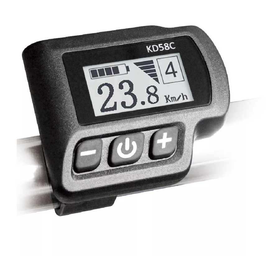
Product name and Model Electric Bicycle Intelligent Display, Model: KD58C. Specifications ● 24V/36V /48V Power Supply ● Rated current: 10mA ● The maximum working current: 30mA ● Off-state leakage current: <1μA ● Working temperature: -20 ~ 60 ℃ ● Storage temperature: -30 ~ 70 ℃... -
Page 5: Function Summary And Button Definition
Function Summary and Button Definition ◆Function Summary KD58C has a lot of functions to meet the users’ needs. The indicating contents are as follows: ● Smart Battery ● Assist-level ●Speed indication (incl. running speed, max speed and average speed) ●Motor-output indicator ●Trip time... -
Page 6: Switching Push-Assist Mode On/Off
→ Max Speed (Km/h). Each state will display for 2 seconds and then automatically returns to current speed interface. Display interface circulation ◆Switching Push-assist Mode On/Off To access the push-assist mode, hold the DOWN button for 2 s, the E-bike will go on at a uniform speed of 6 Km/h and “P”... -
Page 7: Power Indicator
assist Level “4” ◆Power Indicator The output power of the motor can be indicated by below interface. Motor Power Interface ◆Error code Indication If an error occurs in the electronic control system, the error code will appear automatically. See error code definitions in Attached list 1. Error Code Indication ■... -
Page 8: Trip Distance Clearance
General settings interface ◆Trip Distance Clearance Clear Trip means trip distance clearance. Press the UP or DOWN button to choose YES or NO to clear the trip distance. The default value is NO. If you choose YES and press the ON/OFF button to confirm the option, the display will show 'OK' and return to the general settings interface. -
Page 9: Speed-Limit Settings
Wheel Diameter Settings Interface ◆Speed-limit Settings Set LS represents limited speed settings. When the running speed is faster than limited speed, the E-bike system will be switched off automatically. Limited speed range is 12Km/h to 40Km/h. The default value is 25Km/h. To change basic settings, press UP/DOWN to increase or decrease until the desired value is displayed. -
Page 10: Power Assist Level Settings
Personalized parameter settings Interface ◆Power assist Level Settings Power Set means power assist level settings Power assist Level mode In assist level settings, there are 8 modes for your choice: 0-3, 1-3, 0-5, 1-5, 0-7, 1-7, 0-9, 1-9. The default value is 0-5. To select the mode of assist level, press UP/DOWN to increase or decrease until the desired assist level mode is displayed. -
Page 11: Controller Over-Current Cut Settings
PAS Ratio Interface ◆Controller Over-current Cut Settings Current Set represents controller over-current cut settings. The current value can be changed from 7.0A to 25.0A. To change basic settings, press the “+” or the “-” button to increase or decrease the value of the current. -
Page 12: Slow Start Up Settings
◆Speed Sensor Settings Speed Sensor represents speed sensor settings. The default value is 1 To change speed sensor settings, press the “+” or the “-” button to choose the quantity of magnet heads (the range is from 1 to 15). To store a changed setting, hold the “ON/OFF”... -
Page 13: Power-On Password Settings
◆Power-on Password Settings P2:0000 represents power-on password settings. The default password is 1212. After accessing the power-on password settings, press UP/DOWN to modify the value and press ON/OFF to confirm digit one by one until the correct 4-digit password is completed. -
Page 14: Recover Default Settings
■ If there is not any operations in one minute, display will exit the settings state automatically. Recover default settings dEF means recover default settings. Press both the UP and ON/OFF button for 2 s to enter recover default settings. Press the UP or DOWN button to choose Y or N. Y means that recovers default settings. -
Page 15: Connection Layout
Wire connection layout Connector wire sequence Connector to controller display end connection wire end to display Wire sequence table Wire sequence Color Function Red(VCC) Blue(K) Lock Black(GND) Green(RX) Yellow(TX) ■Some products have wire connection with water-proof connectors, users can not see the color of wires in the harness. Warnings: 1. -
Page 16: Attached List 1 Error Code Definition
Attached list 1: Error code definition Error Code Definition Current Abnormality Throttle Abnormality Motor Phase Abnormality Motor Hall Signal Abnormality Brake Abnormality Communication Abnormality Attached list 2:PAS ratio default value table Level level mode 0-3/1-3 — — — — — —...
Need help?
Do you have a question about the KD58C and is the answer not in the manual?
Questions and answers