Table of Contents
Advertisement
Advertisement
Table of Contents

Related Manuals for Key-Disp KD58C


Summary of Contents for Key-Disp KD58C
-
Page 2: Table Of Contents
Contents Product name and model ....................1 Specifications ......................... 1 Appearance and Size ..................... 1 Function Summary and Button Definition ..............2 ◆Function Summary ....................2 ◆Button Definition ..................... 2 Assembly ........................2 Function Area Distribution ..................... 2 General Operation ......................2 ◆Switching the eBike On/Off ................... - Page 3 Quality assurance and warranty scope................. 9 Connection layout ......................9 Operation Cautions ...................... 10...
-
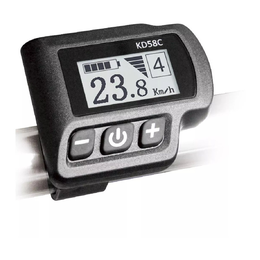
Page 4: Product Name And Model
Product name and model Electric bicycle intelligent display, model: KD58C. Specifications ● 24V/36V /48V Power Supply ● Rated current: 10mA ● The maximum working current: 30mA ● Off leakage current: <1uA ● The supply controller working current: 50mA ● Working temperature: -20 ~ 60 ℃... -
Page 5: Function Summary And Button Definition
Function Summary and Button Definition ◆Function Summary KD58C can provide a lot of functions to fit the users’ needs. The indicating contents are as following: ● Smart Battery indicator ●Assistance-level indication ●Speed indication (incl. running speed, max speed and average speed) ●Motor-output indicator... -
Page 6: Switching Push-Assistance Mode On/Off
Speed (Km/h) → Max Speed (Km/h). Each state will display for 2 seconds and then automatically returns to the Running Speed interface. On the condition that the speed is 0 km/h, Total Distance will be added to the circulation interface. The circulation interface of the condition that the speed is 0 km/h ◆Switching Push-assistance mode On/Off To access the push-assistance mode, hold the DOWN button for 2 s, the eBike will... -
Page 7: Power Indicator
Assistance Level “4” ◆ Power Indicator The out power of the motor can be indicated by the display. Motor Power Indicator Interface ◆ Error code Indication If there are errors about the electronic control system, the error code will appear automatically. -
Page 8: Trip Distance Clearance
◆ Trip Distance Clearance Clear Trip means single trip distance clearance. Press the UP or DOWN button to choose YES or NO to clear the trip distance. The default value is NO. If you choose YES and press the MODE button to confirm the option, the display will show OK and return to the general selection settings interface. -
Page 9: Battery Power Bar Settings
desired value is displayed. To store a changed setting, hold MODE for 2 s and the display will display OK then returns to general selection settings interface . Limit Speed Settings Interface ◆ Battery Power bar Settings VOL represents voltage settings. Each bar represents a voltage value. 5 bars voltage values must be entered one by one. -
Page 10: Pas Ratio Settings
PAS Mode option Interface PAS Ratio settings To modify the value of PAS ratio can match the different requirements. For example, the range is “45-55 percent” of 1 level, bottom value can be modified and the default is 50 percent. Press the UP or DOWN button to increase or decrease the number. -
Page 11: Power-On Password Enable/Disable
Power-on Password Entering Interface Power-on Password Enable /Disable Press the MODE button to enter power-on password modify interface. Press the UP or DOWN button to select Disable or Enable and press the MODE button to confirm. The default value is Enable. If you choose Enable, press the MODE button to enter Power-on Password Modify interface, otherwise exit the power-on password settings interface. - Page 12 hold the MODE button for 2 s to recover default settings, the display shows dEF-00 at the same time, and then return to general display state. The default value is N. Recover Default Settings Interface Quality assurance and warranty scope Ⅰ...
- Page 13 Line sequence table Line sequence Color Function Red(VCC) Blue(K) Lock Black(GND) Green(RX) Yellow(TX) ■ Some wire use the water-proof connector, users are not able to see the inside color. Operation Cautions Be care of the safety use. Don’t attempt to release the connector when battery is on power.
Need help?
Do you have a question about the KD58C and is the answer not in the manual?
Questions and answers