Key-Disp KD718 User Manual
The ebike display
Hide thumbs
Also See for KD718:
- User manual (16 pages) ,
- User manual (22 pages) ,
- User manual (22 pages)
Table of Contents
Advertisement
Advertisement
Table of Contents

Subscribe to Our Youtube Channel
Related Manuals for Key-Disp KD718


Summary of Contents for Key-Disp KD718
-
Page 2: Table Of Contents
Contents Product name and model................................. 1 Specifications..................................... 1 Appearance and size................................1 ◆Display appearance and dimension..........................1 ◆Remote ppearance and dimension..........................2 Function summary ..................................3 General operations..................................3 ◆Switch E-bike system ON/OFF............................3 ◆Display interface.................................3 ◆Switch push-assistance mode ON/OFF......................... 4 ◆Switch lighting ON/OFF..............................5 ◆Assist level selection................................. -
Page 3: Product Name And Model
Product name and model E-bike Intelligent LCD display Model: KD718 Specifications ● 24V/36V/48V Power Supply ● Rated working current: 10mA ● The maximum working current: 30mA ● Off-state leakage current: <1μA ● Operating temperature: -20℃~ 60℃ ● Storage temperature: -30℃~ 70℃... -
Page 4: Remote Ppearance And Dimension
◆Remote appearance and dimensional drawing (unit: mm) -
Page 5: Function Summary
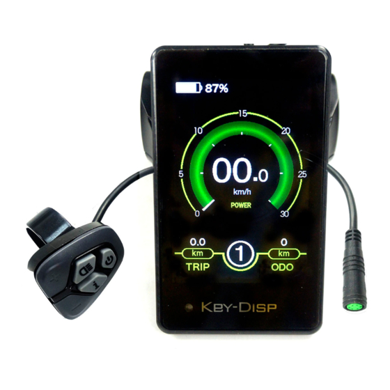
Function Summary KD718 has many functions to meet riders’ needs, the indication elements are as follows: ● percentage Battery and battery ● Motor power ● Power assist level ● Speed indication (incl. current speed, Max. speed and Avg. speed) ●... -
Page 6: Switch Push-Assistance Mode On/Off
Display Indication Cycle Interface ◆Switching Push-assistance Mode On/Off To activate the push-assistance function, press and hold the “-” button on the remote. After 2 seconds, E-bike is activated to go at a uniform speed of 6 Km/h while the screen displays The push-assistance function is switched off as soon as you release the “-”... -
Page 7: Switch Lighting On/Off
◆Switching the Lighting On/Off To switch on E-bike front light or rear light, briefly press the “ ” button on the remote. The display backlight brightness is automatically reduced while the screen displays Likewise, briefly press the “ ” button again, the bike front light or rear light can be switched off and display backlight recover its brightness. -
Page 8: Battery Indicator
◆Battery Indicator he battery percentage info-graphic indicates current battery power.The battery frame is full of a specified color such as green color or white color when the battery is in high voltage. When the battery is in low voltage, battery frame will flash at the frequency of 1HZ to give a notice that the battery needs to be recharged immediately. -
Page 9: Error Code Indication
USB connection USB Connection Indication Interface ◆Error Code Indication The components of the E-bike system are continuously and automatically monitored. When an error is detected, the respective error code is indicated in text indication area. Refer to detailed definition of the error codes in Attached list 1. Error Code Indication Have the display inspected and repaired when an error code appears. -
Page 10: Display Setting
DisPlay Setting Press the On/Off button to switch on the display. To access Setting page, hold both the “+” button and the “-” button for 2s. Setting Interface ▉All the Settings are operated in the case of a parked E-bike. ◆Unit km/mile Conversion Toggle Unit represents unit settings. -
Page 11: Backlight Brightness Settings
◆Backlight Brightness Settings LCD Luminance represents backlight brightness. 100% is the highest brightness. The less the percentage, the lower the backlight brightness. To modify the backlight brightness, press the “+” button or the “-” button to choose the desired percentage. To store a changed setting, briefly press the “i”... -
Page 12: Soc View Settings
◆SOC View Settings SOC view represents 2 display methods of remaining battery capacity. One is by the percentage and the other is by the Voltage value. Press “+/-” button to choose the desired display method. The default view method is by the percentage. To store a changed setting, briefly press the “i”... -
Page 13: Al Sensitivity Settings
◆AL sensitivity AL sensitivity represents Ambient Light Sensor settings. The sensitivity of AL sensor ranges from 1 to 5. The default value is 3. It can help with adjusting the screen brightness as per the ambient light conditions automatically. When you ride the bike at night or in a place where there is a lack of light, the display backlight and bike light will be turned on automatically. -
Page 14: Power-On Password Modifications
To enable a power-on password, choose ON and press “i” button to confirm and input the current password or default password’1212’. Press the “+”or the “-”button to change the number and press the “i”button to confirm digits one by one until the correct password( current password or default password’1212’... -
Page 15: Advanced Settings
Advanced Settings After General Settings (DisPlay Setting) is done, Press Back to return Setting page. Press UP/DOWN button to choose Advanced Settings and press “i” button to enter Advanced Settings page. ◆Wheel Diameter Settings Wheel represents wheel diameter settings. To change basic settings, press the “+” or the “-” button to increase or decrease until the desired value is displayed. -
Page 16: Battery Info
◆Battery Info. Press Battery info for more information and status of the battery you are currently using. ◆Error Code Press Error code for detailed information of last 10 errors in the record. ◆Exit Settings In the settings interface, 1. Briefly press the “i” button is to confirm and store a changed setting but stay within current setting menu. -
Page 17: Wire Connection Layout
3. Don’t modify system parameters to avoid parameter disorder. 4. Make the display repaired when error code appears. This manual instruction is a universal version for DISPLAY KD718. Some versions of this display may be different from specification to specification as to the software. Please... -
Page 18: Attached List 1:Error Code Definitions
Attached list 1:Error code definition Error Code Definition Current Abnormality Throttle Abnormality Motor Phase Abnormality Motor Hall Signal Abnormality Brake Abnormality Communication Abnormality Attached list 2:Assist level ratio defaults Level Level mode 0-3/1-3 — — — — — — 0-5/ 1-5 —...
Need help?
Do you have a question about the KD718 and is the answer not in the manual?
Questions and answers
My KD 718 does not have the "Handle S.L." function. Can the display software be updated?