Table of Contents
Advertisement
Advertisement
Table of Contents

Related Manuals for Key-Disp KD218


Summary of Contents for Key-Disp KD218
-
Page 2: Product Model
Product model E-bike Intelligent LCD display Model: KD218 Specifications ● 24V/36V/48V Power Supply ● Rated working current :10mA ● The maximum working current: 30mA ● Off-state leakage current: <1μA ● Operating temperature: -20℃~ 60℃ ● Storage temperature: -30℃~ 70℃ Appearance and Size... -
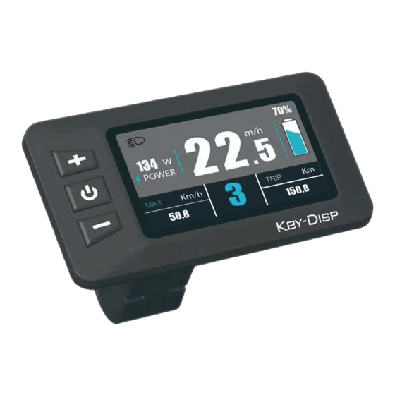
Page 3: Functional Area Distribution
Motor power Speed digital display Mode option Trip km Mode reminder PAS level/Push assist Function Summary KD218 has many functions to meet the Users’ needs. The indicating contents are as follows: ● percentage Battery and battery ● Motor Power ●... - Page 4 ◆Display Interface After switching on the E-bike system, the display will show Current Speed and Trip Distance by default. Press the “MODE” button will show more riding data shown below: Max. Speed (Km/h)→ Avg. Speed (Km/h) →Trip Time (Min.) →ODO(km)→Max. Speed(Km/h) Display interface...
- Page 5 ◆Switching Push-assist Mode On/Off To activate the push-assist function, keep holding “-” button. After 2 seconds , E-bike is activated to go at a uniform speed of 6 Km/h while the screen displays The push-assist function is switched off as soon as you release the “-” button. The E-bike system stop the power output immediately.
- Page 6 ◆Switching the Lighting On/Off To switch on E-bike headlight, hold the “UP” button for 2s. The backlight brightness is automatically reduced. Likewise, press the “UP” button for 2s, the bike light can be switched off. Switching the Lighting Mode On/Off Interface ◆Assist Level Selection Press "+"...
- Page 7 ◆Battery Indicator he five battery bars represent the capacity of the battery.The five battery bars bright when the battery is in full voltage. When the battery is in low voltage, battery frame will flash at the frequency of 1HZ to give a notice that the battery needs to be recharged immediately.
-
Page 8: General Settings
◆Error Code Indication The components of the E-bike system are continuously and automatically monitored. When an error is detected, the respective error code is indicated in text indication area. Here is the detail message of the error code in Attached list 1. Error Code Indication ■Make the display repaired when an error code appears. - Page 9 Setting interface ▉All the Settings are operated in the case of a parked E-bike. ◆Trip Distance Clearance Clear Trip represents trip distance clearance setting. To clear trip distance, press the “+” button or the “-” button to select the Yes or No. Yes represents clearing a single ride distance.
- Page 10 To store a changed setting, press the “MODE” button and then exit Display settings. The default value is “Metric(km)”. Mile and Kilometer Conversion Settings Interface ◆Wheel Diameter Settings Wheel Diameter represents wheel diameter settings. To change basic settings, press the “+”...
- Page 11 To store a changed setting and exit General Parameter Settings, hold the “MODE” button for 2s Limit Speed Settings Interface ◆Battery Power Bar Settings Set Voltage represents voltage settings. Each bar represents a voltage value. 5 bars voltage values must be entered one by one. For example, VOL 1 is first bar voltage value. The default value is 31.5V.
- Page 12 desired mode, and then press the “MODE” button to confirm, then access the General settings page automatically. PAS Mode Option Interface PAS Ratio Settings To modify the value of PAS ratio, press the "+" button or "-" button to choose the desired value, and then press the "i"...
- Page 13 To change basic settings, press the “+” or the “-” button to increase or decrease the value of the current. To store a changed setting, hold the “MODE” button and then return to previous menu. Current Settings Interface ◆Power Assistant Sensor Settings Assistant num represents the sensitivity of PAS settings.
-
Page 14: Power-On Password Settings
of magnet heads (the range is from 1 to 15). To store a changed setting, hold the “MODE” button and then return to previous menu. Speed Sensor Selection ◆Backlight Brightness Settings Set Backlight represents backlight settings. Level “1” is low brightness, Level “5” is high brightness. -
Page 15: Power-On Password Enable/Disable
UP/DOWN to shift from ‘OFF’ to ‘ON’. Refer to below steps to toggle ON and OFF. Power-on password input settings interface ◆Power-on password enable/disable In “Start PassWord” interface, choose ‘ON’ and short press( less than 0.5S) MODE to confirm. Meanwhile, display interface prompts for a password. Press UP/DOWN button to shift numbers from 0 to 9 and press MODE to confirm and input the next digit. - Page 16 ◆Password Reset. When password is enabled. ‘Reset password’ will add to Password interface. Press(less than 0.5s) UP/DOWN button to choose ‘Reset Password’ and press( less than 0.5s) MODE to confirm. Meanwhile, the interface prompts for current password input. The display will be powered off automatically when the password is entered incorrectly after 10 inputs.
- Page 17 ◆ Password Disable In “Start PassWord” interface, choose ‘OFF’ and short press( less than 0.5S) MODE to confirm. Meanwhile, display interface prompts for a password. The display will be powered off automatically when the same password is entered incorrectly after 10 inputs. When a correct password is input, the display will give a prompt of ‘password function disabled’.
- Page 18 Connector wire sequence Connection wire end Connector to controller Display end to display end wire sequence table Color Function Wire Red(VCC) ﹢ Lock Blue(K) Black(GND) ﹣ Green(RX) Yellow(TX) ■Some products have wire connection with water-proof connectors, users can not see the color of wires in the harness. Warnings: ◆Use the display with caution.
- Page 19 Attached list 1:Error code definition Error Code Definition Current Abnormality Throttle Abnormality Motor Phase Abnormality Motor Hall Signal Wire Abnormality Brake Abnormality Communication Abnormality Attached list 2:PAS level ratio default value table level PAS level options 0-3/1-3 — — — —...
Need help?
Do you have a question about the KD218 and is the answer not in the manual?
Questions and answers