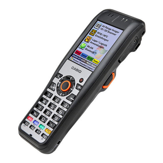
Casio DT-X200 Series Software Manual
Hide thumbs
Also See for DT-X200 Series:
- User manual (72 pages) ,
- User manual (19 pages) ,
- Service manual (85 pages)

Subscribe to Our Youtube Channel
Related Manuals for Casio DT-X200 Series


Summary of Contents for Casio DT-X200 Series
- Page 1 CASIO DT-X200 Series Software Manual (Version 1.03) CASIO Computer Co., Ltd. Copyright ©2015. All rights reserved. June 2015...
-
Page 2: Table Of Contents
Table of the Contents Product Overview·························································································································································6 Basic Description··················································································································································6 1.1.1 List of Models·················································································································································6 1.1.2 Name of parts·················································································································································7 Software Configuration ································································································································8 Microsoft Windows Embedded Compact 7···············································································8 1.2.1 1.2.2 Standard application composition·································································································9 1.2.3 Option software structure ······················································································································ 12 Function ····································································································································································· 13 Display································································································································································· 13 Display control········································································································································... - Page 3 Bluetooth···························································································································································· 78 Basic specifications····························································································································· 79 2.14.1 2.15 Wireless LAN ··················································································································································· 83 Function summary································································································································ 83 2.15.1 Casio expanded features ·················································································································· 85 2.15.2 Wireless LAN settings ························································································································ 88 2.15.3 Introduction ································································································································································· 95 System menu······················································································································································· 95 Perform Initial Setup···································································································································· 97 Welcome Wizard····································································································································· 97 3.2.1...
- Page 4 WLAN Barcode Setting Tool ········································································································· 148 3.10.3 3.11 Bluetooth Connection ······························································································································ 149 Bluetooth Manager ····························································································································· 149 3.11.1 3.12 Backup User Data ······································································································································· 150 Backup Tool············································································································································ 150 3.12.1 3.13 Duplicate a Terminal·································································································································· 156 3.13.1 Copy Devices Tool······························································································································ 156 3.14 Automatically Install Software············································································································· 164 Auto Setup···············································································································································...
- Page 5 Standard with the application list ·············································································································· 204 Optional Software List ··································································································································· 207 Editorial Record Manual Date edited Page Content Version no. 1.00 March 2015 New version 1.01 March 2015 38,39 “2.8.3 Reset and resume control”update 24,27 “2.4 Audio/ buzzer” , “2.5 LED”update "2.10 Imager"...
-
Page 6: Product Overview
1. Product Overview 1.1 Basic Description This chapter describes the overall composition of the DT-X200 unit and its software. 1.1.1 List of Models The major features integrated in each model of the DT-X200 series are shown below Scanner Product name Imager DT-X200-10E... -
Page 7: Name Of Parts
The main item name of DT-X200 body is as follows. Scanner, NFC Reading device Speaker Indicator 1 Indicator 2 Micro SD Card slot. L Trigger R Trigger (R Enterkey) (L Enterkey) Note : Please refer to "DT-X200 series Hardware manual" about details. -
Page 8: Software Configuration
1.2 Software Configuration The OS on the unit is Microsoft Windows Embedded Compact 7 (WEC7). It also has Casio control software and various applications installed. The main software configuration is as follows: Microsoft Windows Embedded Compact 7 1.2.1 This is the successor OS to Windows CE 6.0, designed for space-saving devices. -
Page 9: Standard Application Composition
Standard application composition 1.2.2 The application functions installed as standard on the DT-X200 are as follows: (1) Start-Settings Menu Name 説明 1 Bluetooth Performs power settings and device scans. 2 CPU Speed Sets the CPU operating speed. 3 IME setting Sets display/ hide for the IME toolbar. - Page 10 Name Description 22 Power Set power management options. Sets up buzzer sound to enabled/disabled, and its sound volume 23 Buzzer to low/medium/high. 24 Sounds & Notifications Sets sound types and their volume levels. 25 Mouse Adjusts double click interval. 26 Input panel Changes the current input method and options.
- Page 11 15 Laser scanner demo Demonstrates the laser scanner reading functions. 16 Notification Demo Demonstrates the buzzer and vibration. 17 Cmail Mailer software by Casio. 18 Internet Explorer Displays Web pages for Internet and Intranet. 19 TextEditor A simple rich text editor.
-
Page 12: Option Software Structure
Works through SMS from a remote location to protect data. A tool to upload and download files between the PC server 9 LMWIN and the terminal. 10 Media Security II Security for SD cards using AES. 11 CASIO Terminal Manager (CTM) A tool for terminal management. -
Page 13: Function
2. Function This document explains the details of the functions of the unit and its options. 2.1 Display Information is displayed on a 2.7 inch QVGA screen size (320 dots vertically x 240 dots horizontally). The main functions are as follows. ①... - Page 14 (2) Backlight auto dimming (only under battery power) - If the terminal is left over in idle state, with no key or touch panel input, the backlight will dim automatically (the auto dimming function is only enabled under battery power). When key or touch panel input resumes, the dimmed state is canceled and the display reverts to normal brightness.
-
Page 15: Key Control
2.2 Key control This section explains the functions of the control keys, input keys, function keys, and trigger keys. The function keys correspond to F1~F8, and the Fn key displays the control keys. Key layout 2. Cursor keys 5. Control keys (L-Multi、R-Multi)... -
Page 16: Key Types
Key types 2.2.1 The usable keys are as follows: Key name Basic operation Control keys Power key Switches the power on and off. Enter ( ) Confirms input. Transitions the input mode to F. Deletes one character in front of the input cursor. L-Multi Start the application (system only). - Page 17 (3) Key mode transition suppression Suppresses key mode transitions. When the mode is switched sequentially through [1]->[A]->[a]->[1] (repeating), and [A], [a], and [P] are set as suppressed, switching changes to run sequentially through [1]->[1] (repeating). Setting can be made from the application by using a system library. For details, refer to the System Library Manual.
- Page 18 (7) Input switch key control Press the character key to switch the input mode. The current key mode is indicated on the task tray title bar. Display mode Content Numeral mode Single-byte numeral input Single-byte uppercase alphabet input Alphabetic uppercase character mode Single-byte lowercase alphabet input Alphabetic...
-
Page 19: Key Assignment
Key assignment 2.2.2 The following are the key codes and function assignments. (1) Control keys Specialized operations Operation specification Remarks ---- Specialized key operation (toggle) Fn mode is released when the next key input is made. L-Multi key L-Multi In character input mode L-Multi key L-Multi key... - Page 20 (2) Function keys Specialized operations Operation specification Remarks Performs as ALT key. In character input mode Performs as ALT key. Performs as ALT key. Performs as ALT key. In Fn mode Performs as Shift + TAB keys. In character input mode Performs as Shift + TAB keys.
- Page 21 (3) Trigger keys Specialized operations Operation specification Remarks R-trigger In character input R trigger key mode R trigger key R trigger key In Fn mode R trigger key L-trigger In character input L trigger key mode L trigger key L trigger key In Fn mode L trigger key Center...
- Page 22 Specialized operations Operation specification Remarks In character input “6” mode In Fn mode Brightens the backlight In character input “7” mode PQRS pqrs In Fn mode Initiates application registered in the registry below. [HKEY_LOCAL_MACHINE¥HARDWARE¥DEVICEMAP¥K EYBD] Fn7LaunchPaht:sz (path of the application to be initiated.) In character input “8”...
-
Page 23: Touch Panel
2.3 Touch panel The touch panel can be used to perform input operations from the screen. The main features are as follows: Calibration data values are maintained even without battery power. (Be sure to calibrate the touch panel once prior to using it.) The unit is equipped with a software keyboard function. -
Page 24: Audio/ Buzzer
2.4 Audio/ buzzer The functions are as follows: Mic function – Use this to record sound to the Voice Recorder. (Monaural) Use conversation over WAN (only models equipped with WEH6.5 Pro) The output target during – talk is the receiver. Speaker function Use this to play audio memos and WAV files. -
Page 25: Audio
Audio 2.4.1 Audio supports WAV playback, voice recording, and other functions. Stereo data is converted to monaural for output. Voice Recorder is an installed sound-related application. - Play 11.02 22.05 44.1 Sampling frequencies Monaural Stereo Sampling frequencies other than those above are not supported Stereo/ monaural 8bit or 16bit In reality, the integrated monaural speaker does not output sound in stereo. -
Page 26: Buzzer
Buzzer 2.4.2 The buzzer outputs sounds from the speaker for scan complete, key click, tap sound, alarm sound, warning sound, and other optional sounds. It does not output through headphones. Use the audio driver function to output through headphones. Buzzer sounds have the following 4 types of attributes. The default values are as stated in the table below. -
Page 27: Led
2.5 LED There are two LEDs, a charge complete LED (the left side) and an LED for user notice (the right side).These can be turned on and off individually. The functions of each are as follows: (1) Charge completion LED (the left side) This is for recharge status, notifying that power is being supplied for charging (it cannot be lit by user instructions). -
Page 28: Led Control
LED control 2.5.1 The main functions are as follows. For details of the library, refer to the System Library Manual. (1) User notification LED This is used for alarm notification, etc. Use as the scanner scanning LED has priority for lighting. This LED can be controlled from the OS, which can make it light for a set period. - Page 29 (4) Bluetooth connection status LED This is used for notification of Bluetooth connection status. Lighting specification Item Specification Connection established via On in blue for 1 second, off for 2 seconds wireless LAN Time continuously ON - Use as the scanner scanning LED has priority. User access from a private library is also possible. (5) User-defined LED This is used for other notifications defined by the user.
-
Page 30: Vibrator
2.6 Vibrator Vibrator (vibration) operates for scan complete, alarm occurrence, warning occurrence, wireless incoming call, and user-defined purpose. Each vibration operation can be turned on and off individually. The functions of each are as follows: Vibrator control 2.6.1 There is one level of vibration intensity, and the vibration interval can be set in two different patterns, the default setting and a user-defined setting. -
Page 31: Storage
2.7 Storage This unit has slots for fast, high-capacity Flash Disks and Micro SD cards. Flash disk 2.7.1 This is recognized by the OS as a storage disk, and is displayed in the root directory as the “FlashDisk” folder. The FlashDisk can be used for saving files such as data files and program files. Once data has been written to FlashDisk, it is retained even without battery power. -
Page 32: Sd Card
SD card 2.7.2 This unit supports Micro SD cards (maximum capacity: 32GB, SDHC standard). When a Micro SD card is inserted, it can be used for memory expansion or external storage. (1) Micro SD card slot Supported Folder Slot type capacity name Access width... -
Page 33: Precautions
Precautions 2.7.3 The following operations on FlashDisk and Micro SD card risk corrupting some or all of the data they contain. (1) Reset during data writing If a reset request is issued during data writing, and Off process is attempted within the specified period. -
Page 34: Power Control
2.8 Power control This section explains the power control functions. Function Overview Power On Turns the DT-X200 unit on. There are 5 types of factor that turn power on. Power Off Turns the DT-X200 unit off. There are 6 types of factor that turn power off. Memory check Checks the status of memory after power is turned on. -
Page 35: Power On/ Power Off
Power On/ power Off 2.8.1 The factors which turn unit power On and Off (suspend and resume) are as follows. (1) Power ON Factors ① Power is turned on by pressing the Power key on the unit. ② Power is turned on automatically by the Alarm function at the specified time. ③... - Page 36 (4) Temperature restriction control When external temperature is high and the unit’s devices are operating at full capacity (high CPU speed, continuous wireless communications) etc., the internal temperature of the unit rises and eventually a warning is issued and the power is turned off to protect the unit. In that case, either turn off the power and leave the terminal unused for a while, or move it to a location where the surrounding air temperature is cooler.
-
Page 37: Power Key Control
Power key control 2.8.2 The Power key must be pressed for approximately one second for the system to recognize turning on the power. The Power key must be pressed for approximately one second for the system to recognize turning off the power. (1) Disabling the Power key after turning on the power After turning on the power, the Power key will be disabled for a certain period of time. -
Page 38: Reset And Resume Control
Reset and resume control 2.8.3 When a power on factor occurs, resume or reset is used to start the system. A reset clears program execution status.Therefore, data on the RAM in work is discarded, because there is a possibility that in the middle of writing a file is corrupt, you need to be careful.Resume, will return to the program execution state before power OFF. - Page 39 (4)User disk clear Press the Reset button for a period of one second or longer while the Fn key, CLR key, and the period key are pressed.Full reset and similar warning screen appears. Operation is also the same.Root disk (¥, ¥ Windows folder, etc.) and the registry, is initialized to the factory default state.After formatting the FlashDisk, you can start it and then re-load the OS to RAM do the reset process.
-
Page 40: Power-Saving Control
Power-saving control 2.8.4 There are the following types of power-saving control. (1) Sleep The CPU transitions into idle state for power saving when the system and applications have nothing to do and are waiting for events. The peripheral devices are operating. (2) Auto Power OFF (APO) The system turns off automatically if there is no activity (keys, touch panel) for a set period. - Page 41 (5) Virtual off (wireless standby) Virtual Off is a wireless standby state due to low power consumption. To the user, the unit behaves as if it is off (suspended). Internally, the terminal is running normally but it seems to be turned off (suspended) - nothing is displayed and you cannot make key inputs.
-
Page 42: Laser Scanner (Barcode)
2.9 Laser scanner (barcode) Scannable codes 2.9.1 The following barcodes can be scanned using the laser scanner. List of scannable codes Minimum and Barcode Check digit maximum digits EAN, JAN, UPC-A Modulus 10, weight 3 8 (fixed) 13 (fixed) EAN, JAN, UPC-A add-on Modulus 10, weight 3 10 (fixed) 18 (fixed) - Page 43 *2 RSS Expanded The maximum digit count for just numeric data is 74 digits, or the maximum digit count for just alphabet data is 41 digits. *3 Minimum digits for Code39 The no. of minimum digits can be set to one digit only when scanning Code39 symbology is enabled.
-
Page 44: Scanning Method
Scanning method 2.9.2 The laser scanner has “scanning state” (emits a laser beam to read a barcode) and “standby state” (scanning is halted and the terminal remains in a standby state). These two states are controlled to start and stop barcode scanning. Scanning Description Conditions for scanning to end... -
Page 45: Scanning Conditions
Scanning conditions 2.9.3 Conditions that allow scanning a barcode symbology in specific modes can be set for each readable symbology. Readable symbology codes Barcode symbologies that are enabled or disabled for scanning can be specified. If only specific symbologies are to be scanned, set “Enable” for scanning on these barcode symbologies only and “Disable”... - Page 46 *1 GS1-128 code is also scannable. The name of EAN-128 was changed to GS-128 in January 2006 Validation count Validation is carried out for a specified number of times to check if scanned data is valid, and then the data is output only if it is valid. The number of validations can be set either on the Control Panel or using the laser scanner library.
-
Page 47: Scanning Result Output Format
Scanning result output format 2.9.4 Formats for outputting results of scanned barcodes can be set. (1) Setting output formats The output formats illustrated below can be set for each code. Barcode Standard No. of Output format Remarks digits JAN-13 FFMMMMMNNNNNC" F: Country flag EAN-13 FFMMMMMNNNNNC"... - Page 48 Barcode symbology Standard No. of Output format Remarks digits Code39 3~50 SBBB・・・・・BBCS” A: Post-conversion ASCII data (with full 3~50 SAAA・・・・・AACS” ASCII conversion) 1~48 BBB・・・・・・BBC" B: Post-conversion ASCII data (without ASCII 1~48 AAA ------ AAC” conversion) (*1) C: Check digit (mod 43) Becomes data if there is no check digit attached.
- Page 49 * In WEH6.5 Pro models, the connection destination system for remote desktop, correct output of data that includes characters expressed in combination with the Shift key, such as capital letters and symbols, requires setup to enable the following settings in the registry. Registry path name: HKEY_LOCAL_MACHINE¥Drivers¥CASIO¥Laser Item name: RDPOutput Data format: DWORD...
- Page 50 Save to memory method (output to OBR buffer) When a bar code is scanned, its decoded data, including the barcode symbology and data size, are stored in the OBR buffer, which is a data storage memory area in the driver. The saved data can be retrieved by a function supplied from the library.
- Page 51 (5) Setting unique specialized operation symbology The terminal can be set to perform special actions when various barcode symbologies are scanned and satisfy certain conditions. The code types, conditions, and operation content are as follows. Barcode Conditions Operation Code128 When barcode data Scanned barcode data including the FNC2 includes FNC2 function character is temporarily stored in the...
- Page 52 (6) Control characters conversion output If the scanned barcode included a control character, that control character can be replaced with another character, or it can be deleted, before output. The character that has not been replaced or deleted yet can specify multiple arbitrary control characters. The character after replacement can specify multiple arbitrary characters, other than control characters.
-
Page 53: Scan Result Notification
Control character conversion example The example of conversion after barcode data scanning is as shown below. Control character conversion example OBRDRV_R.ini Barcode data before conversion Barcode data after conversion [ConvSrc] Code01=0x1D Code02=0x0A [ConvDst] 01230x0A45670x1D890x0201 0123@4567/8901 Char01=’/’ Char02=’@’ (Underlined portion is represents - 0x0A is replaced by ‘@’, and the control character) 0x1D by ‘/’. -
Page 54: Expanded Functions
*2 OBR buffer overrun This means scanning takes place while data for 9 labels was already stored in memory in the OBR buffer, when the “OBR buffer output” was the scanned data output method. Expanded functions 2.9.6 (1) Laser emission width control If the laser emits on barcodes located near each other, scanning may fail. - Page 55 (2) Laser focus If scanning takes place with the laser beam emitted onto multiple bar codes located near each other, it can be difficult for the user to distinguish which barcode was correctly scanned. In that case, when the laser focus function is enabled, the scanned barcode is indicated by the laser when barcode scanning is successful, and a notification is sent to the user saying which barcode was scanned.
-
Page 56: Power Control
Power control 2.9.7 (1) Module power control during non-use In order to save power, the scanner module is switched to standby mode when laser light is not being emitted. (2) Virtual Off The barcode scanner does not perform any particular processes. Even if the device terminal transitions to Virtual Off, the barcode scanner performs the same process as when it is on. -
Page 57: Imager (1D/2D Codes)
2.10 Imager (1D/2D codes) This section explains the specifications for scanning 1D and 2D barcodes. Barcode scan specification 2.10.1 The symbols which can be scanned by the imager are as follows. (1) 1D code (barcode) Scan Check Check Code No. of Character Character Other functions... - Page 58 (*1) ISBT code is recognized as Code128. (*2) The name of code EAN128 (UCC/EAN128) has been changed to “GS1-128”. (*3) When scanning Code32, set to enable scanning of both Code32 and Code39. - Reading the number of scanned digits Figures outside brackets are the numbers of readable digits. Figures inside brackets are numbers of settable digits for the library and Control Panel.
- Page 59 (3) 2D code (Matrix code) Check Scan Check Code Character Remarks No. of digits Character output 1~2000 Always Always Aztec (1~3750) enabled disabled Always Always Model 2 only 1~1500 QR Code (*1) (1~3500) enabled disabled 1~35 Always Always Micro QR Code (1~3500) enabled disabled...
-
Page 60: Scanning Method
Scanning method 2.10.2 (1) Standard scanning One symbol is read and the data is output. This scan method is the one normally used. (2) Multistage scanning This function decodes continuously while the trigger key is held down. Symbols that have been decoded once are never scanned again. -
Page 61: Scanning Conditions
Scanning conditions 2.10.3 Conditions can be specified for scanning symbols. (1) Specifying symbols which are valid for scanning Types of symbols can be specified as valid or invalid for scanning. If only specific symbols are to be scanned, set “Enable” for scanning on those symbols only, to reduce scan processing time. Default setting All invalid (2) Specifying readable digits... -
Page 62: Scan Result Notification
Scan result notification 2.10.4 This function notifies when symbol scanning is complete. (1) Notification by indicator LED When scanning is complete, or when it has failed, the indicator LED (the LED on the right front of the terminal) lights. The following patterns can be set. Scan interrupted Scan Scan... -
Page 63: Expanded Functions
Expanded functions 2.10.5 This function adjusts the scanning speed to facilitate scanning of hard-to-read symbols. (1) Decoding deliberation levels The level of deliberation with which symbols are scanned can be set at five different levels. Setting the level to Very Quick or Quick limits the symbols which can be decoded but increases the decoding speed. - Page 64 (2) Print weight adjustment function This function improves scanning of symbols with either thick or thin bars. Seven setting levels are available. While no setting is required under normal conditions, this scale can be adjusted to improve scanning performance under difficult conditions. Fine Default Thick...
- Page 65 (4 ) Decode B/W reverse function This function is for scanning symbols (B/W reverse symbols) printed in white on black, in contrast to normal symbols. B/W reverse symbols can be scanned when B/W reverse mode is specified. Configuration Description Remarks No B/W reverse Scan normal symbols (printed in black on white).
- Page 66 (7) Focus setting(Automatic linking of combined symbols) This function is used to execute auto focus or manual focus at scanning symbols. When you use this function in Full Range Imager model, you can scan symbols from near distance and long distance. You can set "Auto Focus"...
-
Page 67: Basic Functions
Basic Functions 2.10.6 (1) Imaging capture This function captures image data. It outputs two-tone of 256-level grayscale as image data. When used together with a JPEG library, it can save captured images as JPEG files. Resolution can be lowered for output by downsampling the image. At that stage, the image sizes are as follows. - Page 68 The following four types of symbols are compatible with the sign clipping function. Supported symbols Remarks Code39 Code128 PDF417 Aztec Code (3) Streaming display This function runs the scanner continuously to continuously display the image. When used together with “2.12.1 Imaging Capture”, it can be used as a camera viewfinder. Function Image size Reduction (downsampling)
-
Page 69: Common Functions
Common functions 2.10.7 (1) Illumination aimer The imager device is equipped with an illumination LED and an aimer (either LED or laser) to indicate the scan position. This software can vary their intensities and turn them on and off. When scanning barcodes, the illumination and the aimer light alternately. -
Page 70: Nfc (Near Field Communication)
2.11 NFC (Near Field Communication) Communication with contactless IC cards and RFID tags makes it possible to read and write from and to cards which follow their card standards. 2.11.1 List of cards ready for communication The types of IC card ready for communication, and their commands, are as follows. ISO/IEC14443 TypeA Card type Support command... - Page 71 Card type Support command my-d Light Read Single Block, Write Single Block, Write AFI, Lock AFI, Read Single Block, Write Single Block, Tag-it HF-I Plus Lock Block, Read Multiple Blocks, Write AFI, Write DSFID, Get System Information, Get Multiple block Security Status Read Single Block, Write Single Block, Tag-it HF-I Pro, Tag-it HF-I Standard Lock Block...
-
Page 72: Communication Functions
2.11.2 Communication functions Reading and writing of IC card data is performed by way of contactless communication between an NFC module and an IC card. IC cards are preprogrammed to perform certain operations in response to prescribed commands. When a command is correctly transmitted to an IC card, the card responds to the received command by performing a corresponding operation. - Page 73 Data communication functions Data communication becomes possible once the IC card has been activated by the card polling function. Communication ends once the NFC module has received response information from the IC card in response to a transmitted command, or when the timeout elapses. When the communication is successful, the IC card remains in the activated mode, thus enabling consecutive transmission of other data.
- Page 74 Description The NFC module consumes very little power while it is on. In addition, turning the module on takes time, so if you would like to start communicating with an IC card straight away, please be sure to open the device prior to activating the application. When initiating communication with an IC card, start by performing card polling.
-
Page 75: Expanded Functions
2.11.3 Expanded functions Radio wave auto stop timing notification After successfully activating an IC card using the card polling function, the radio wave transmission will stop automatically if a certain time elapses without any data communication between the NFC module and the IC card. When this happens, it is possible to send a notification to the user application of the time the radio wave transmission stopped, using either a window message or an event. -
Page 76: Usb
2.12 USB This chapter describes about detailed specifications of the USB. (1)Switching USB Switches between USB Client (USB Function) and USB Host. Switching between USB Client (USB Function) and USB Host is carried out by a signal from the cradle. -
Page 77: Lan Cradle Ip Setup
2.13 LAN cradle IP setup IP address information is written into the LAN cradle in advance, so LAN communication can use an IP address linked to the LAN cradle. (1) Operation image Preparation In the kitting phase, the IP address information is written into the LAN cradle. The writing tool is installed on the handy terminal. -
Page 78: Bluetooth
2.14 Bluetooth This section explains Bluetooth functions and specifications. List of functions Function The specification Bluetooth Ver. Master Slave Security/ encryption Simultaneous connection to multiple Bluetooth devices AFH/FastConnection Yes Auto Module PowerClass [Reference] The signal output varies according to the equipped Bluetooth module. Class is defined as follows in the Bluetooth standard. -
Page 79: Basic Specifications
Basic specifications 2.14.1 (1) Basic communication procedures This section explains the basic procedures for using Bluetooth for communication. ⅰ Bluetooth initialization When the Bluetooth tool is started or an initialization function is executed in the library, it will turn on the power to the Bluetooth module and initialize the Bluetooth protocol stack. - Page 80 (2) Communication Profiles The Bluetooth profiles described in the table are supported. Profiles (General Accessible Profile) (Service Discovery Profile) Serial Profile (Client) Serial Profile (Server) (Dial-Up Network) PAN User (Personal Area Networking Profile) HID Host (Human Interface Device) KEYBORD (3) Communication procedures for each profile In Bluetooth communication, there is the possibility of the communication link being cut off by the radio wave environment.
- Page 81 (4) Security This feature supports security functions regulated in the Bluetooth standard. Bluetooth security is divided into authentication and encryption. Security is realized by using PassKey (otherwise known as PIN code). PassKey is a shared (common) authentication key used when forming a connection and trust relationship (bonding) between Bluetooth devices.
- Page 82 (8) Bluetooth power supply status ⅰ Bluetooth power is turned on by the following operation. This is the case if the BluetoothON operation was performed by a tool, and the BTLIB Initialize function was called. ⅱ Bluetooth power is turned off by the following operation. This is the case if the BluetoothOFF operation was performed by a tool, and the BTLIB DeInitialize function was called.
-
Page 83: Wireless Lan
- If the 5GHz W53/W56 frequency band is used, turn the access point stealth setting off. (If stealth is set, the access point cannot be found and no connection is possible). (2) Casio expanded features The following functions are Casio expanded features. - Power saving (Off) - Roaming... - Page 84 (5) Terminology Roaming This function automatically switches access points in an environment where two or more access points with identical SSID code exist. Power saving This saves power by automatically turning off power to the wireless circuit in the module in the terminal when communication does not take place.
-
Page 85: Casio Expanded Features
2.15.2 Casio expanded features (1) Power saving Perform IEEE802.11-compliant power saving operation. A function to turn power saving operation off is provided, but there is no need to turn it off if there are no particular problems. (2) Roaming In an environment where there are two or more access points with identical SSID codes, the roaming function automatically switches to the access point with the better radio wave environment. - Page 86 However, speed reduction must be taken into consideration, and it is necessary to check the state of speed reduction in the actual usage environment. (4) Scan channel selection Restricting the channels to scan suppresses redundant signal output and improves scan time. This channel selection is superseded by country-specific settings and communication standard settings.
- Page 87 In this case, there are multiple access points with different SSIDs on the same site, and the one to connect to is switched automatically due to movement. Comparison Method Connection speed Casio expanded/ Switching TCPIP settings [1] Manual High A different...
-
Page 88: Wireless Lan Settings
As in the table above, if the Casio wireless LAN setting tool is used for setup, the registry information set by the standard MS tool is overwritten on reset. Therefore, Casio settings have priorities. - Page 89 Relationships between settings The basic setting (SSID) can be set in multiple ways at the same time, but with Casio expanded settings and TCPIP settings, all SSIDs have the same setting. Basic settings Casio expanded TCPIP settings (Standard MS or Casio...
- Page 90 EAP-MD5. (*2) Setup is only required if the authentication method is PSK. (*3) This is as follows with MS standard and Casio settings. - MS standard setup (WEC7): Automatic setup (non-stealth with a detected SSID, stealth when SSID is added manually)
- Page 91 - Relationships between security, authentication, and encryption methods The settable combinations are as follows. Security Authentication method Encryption MS standard Casio method setup settings None None None Open Shared EAP-PEAP EAP-TLS EAP-MD5 TKIP EAP-PEAP TKIP EAP-TLS TKIP WPA2 TKIP EAP-PEAP...
- Page 92 (2) Casio expanded settings Item Content Default Wireless LAN power Turn the power of the wireless LAN on or off. OFF supply Power saving Specify “Enable” or “Disable” for power Valid saving. Communication Specify the communication standard. 11abgn standard 11b/g...
- Page 93 Item Content When Reset Full User shipped reset disk clear INI file This file is created when the Casio None Settings Settings When wireless LAN setting tool is used for retained retained shipped setup Registry These are settings for the operation...
- Page 94 (5) Wireless LAN settings INI file The wireless LAN settings INI file can be created with the wireless LAN setting tool. * Operation cannot be guaranteed if it is edited with anything other than the setting tool. File composition Item Content Remarks Storage folder...
-
Page 95: Introduction
3. Introduction 3.1 System menu When you start OS in product shipment state, it will be the main menu below. By treating selected from this menu, program start-up, you will be able to carry out the settings and the like. [Main Menu]... - Page 96 Menu Structure System menu configuration is as follows. Top menu First hierarchy Second hierarchy Third hierarchy 1.Programs 1.File Explorer 2.Command Prompt 3. FLCE 5.Demonstrations 1.Scanner 2.Buzzer / Vibrator 3.Screen 4.NFC Reader 2.Settings 1.System1 1.Owner 2.Clock 3.Error Report 4.Power 5.Volume _Sounds 2.System2 1.CPU Speed 2.Brightness...
-
Page 97: Perform Initial Setup
3.2 Perform Initial Setup Welcome Wizard 3.2.1 (1) Startup screen After the terminal first boots, the following Startup screen will appear. The following settings can be made from here: Touch panel calibration Owner information Date and time Execution Explanation operation... -
Page 98: Date/Time/Alarm Setting
(2) Desktop screen The following Desktop screen appears after Initial Setup is complete. 3.2.2 Date/Time/Alarm Setting Select Start -> Settings -> Control Panel -> Date/Time. Set the current date, time, and timezone on the dialog shown below. After "Setting Password for Date and Time", it will be password input at startup. -
Page 99: Owner Information
3.2.3 Owner Information Select Start -> Settings -> Control Panel -> Owner. Set information about the owner in the following dialog. [Identification]Tab [Notes]Tab Item Explanation Identification Name Specify the name. (Arbitrary input) Company Specify the Company. (Arbitrary input) Address Specify the Address. (Arbitrary input) Work phone Specify the work phone number. - Page 100 [ Network ID ]Tab Item Explanation Network ID User Name This field is for specifying a user name to be used when accessing network resources. Password This field is for specifying a password to be used when accessing network resources. Domain This field is for specifying a domain to be used when accessing network resources.
-
Page 101: Regional Settings
3.2.4 Regional Settings Select Start -> Settings -> Control Panel -> Regional Settings. Open the tabs for Region, Language, and Input, to make detailed settings. [Region]Tab Customize Item Explanation Region Your locale Choose English (United States). Customize Make settings for Number, Currency, Time, and Date. [Language]Tab [Input]Tab Explanation... -
Page 102: Power
3.2.5 Power Select Start -> Settings -> Control Panel -> Power. The dialog below sets the Power Management options. [Battery]Tab [Schemes]Tab Item Explanation Battery Power This tab displays the current status of the main battery Main batteries and the backup battery. Schemes Power Scheme Select the power source for the setting subject, from... -
Page 103: Cpu Speed Setting
[Device Status]Tab Item Explanation Device Status Device Name, Power Level Displays device power levels. CPU speed setting 3.2.6 Select Start -> Settings -> Control Panel -> CPU speed. CPU speed can be changed if the Automatic Save Power mode has been set disabled (this is the default). -
Page 104: Input/Display Settings
3.3 Input/Display Settings Desktop setting 3.3.1 Select Start -> Settings -> Control Panel -> Display. Set Background, Appearance and Backlight. ]Tab ]Tab Background Appearance Item Explanation Background Image Select an image to be displayed in the background. “Browse”button This button displays the file reference dialog, to specify an image to be displayed in the background. -
Page 105: Touch Panel Calibration
Touch Panel Calibration 3.3.2 Select Start -> Settings -> Control Panel -> Stylus. The dialog below can be used for double tapping adjustment and touch screen position calibration. Readjust as necessary. [Double-Tap]Tab [Calibration]Tab Explanation Double Tap Double tap on the grid to adjust the speed of double tapping and distance between points. -
Page 106: Vibrator
Vibrator 3.3.3 Select Start -> Settings -> Control Panel -> Vibrator. Item Explanation Vibrator When making the respective vibrators effective, a check box is turned on. -
Page 107: Keyboard Settings
Keyboard Settings 3.3.4 Select Start -> Settings -> Control Panel -> Keyboard. Make settings concerning keyboard operations. [Repeat] Tab Item Explanation Repeat Enable character Check the check box to enable repeating key entry. repeat. Repeat delay Specify the waiting time period until repeating key entry starts. -
Page 108: Brightness
Brightness 3.3.5 Select Start -> Settings -> Control Panel -> Brightness. Sets backlight brightness, auto dimming, and auto off. [Brightness(Battery)]Tab [Brightness(External)]Tab Item Explanation Brightness(Battery) Battery Power Specify brightness, in one of nine levels, to apply Operation while the battery pack is being used as the power source. - Page 109 [Backlight]Tab [Version]Tab Item Explanation Backlight Auto display dimming when Specify the time period until dimming is enabled. using Turn off backlight when using Specify “Enable” or “Disable” for backlight auto off, as well as a time period until the backlight turns off when enabled, for both battery and AC power situations.
-
Page 110: Mouse Setting
Mouse Setting 3.3.6 Select Start -> Settings -> Control Panel -> Mouse. In the dialog below, the menu sets double-click interval for the stylus (when using the mouse emulator). Double click the grid in the right side of the upper screen to calibrate the double click speed and its interval. -
Page 111: Volume Level Settings
3.4 Volume Level Settings Sounds & Notifications 3.4.1 Select Start -> Settings -> Control Panel -> Volume & Sounds. Sets sound types and their volume levels. [Volume]Tab [Sounds]Tab Item Explanation Volume Slider (Soft,Loud) Sets sound volume levels with a slider at the top of the screen. Enable sounds for Check the check box to enable individual sound items. -
Page 112: Security Settings
3.5 Security Settings There are the following types of security. (1) Setting the terminal password Select Start -> Settings -> Control Panel -> Password, then set the password. Refer to “3.5.1 Terminal Password Settings” about tool operation. (2) Password setting for date and time A password can be set to block access to the date and time settings on the Control Panel, in order to prevent the user from changing those settings on the terminal. -
Page 113: Terminal Password Settings
Terminal Password Settings 3.5.1 Select Start -> Settings -> Control Panel -> Password. From the dialog box below, set the password to input when the terminal starts up. Item Explanation Password Password Input the password according to the password type. Settings Confirm password Input the same value for confirmation. -
Page 114: Setting Password For Date And Time
Setting Password for Date and Time 3.5.2 Select Start -> Programs -> Windows Explorer, then open the Windows folder. (1) Start “passtool” from the window below. (2) From the dialog below, set the password to input when the terminal starts up. Item Explanation Password... -
Page 115: Laser Scanner (1D) Settings
3.6 Laser Scanner (1D) Settings This function only applies to models equipped with a laser scanner (1D). Refer to Chapter 2, “2.9 Laser Scanner (Barcode)” for details of this function. Laser Setting 3.6.1 Select Start -> Settings -> Control Panel - Scanner settings. Use the tool below to change scanner device settings. - Page 116 [Read operation]Tab [Read operation 2]Tab Explanation Read operation Specify the following scanner operations when reading codes. Continuous read or Single read Swing Angle Wide, Swing Angle Middle, or Swing Angle Narrow (Note 1) Enable Laser Focus or Disable Laser Focus (Note 2) ...
- Page 117 [Notification]Tab [Scanning Key]Tab Explanation Notification This tab is specify one of the scanning notification methods listed below. LED light up Buzzer sound Vibrator Scanning Key This tab is to set up “Enable” or “Disable” for the following Trigger keys. ...
- Page 118 [Others]Tab [Version]Tab Item Explanation Others Calibration Button ※ This button displays the OBR calibration screen to set up the calibration of laser beam swing angle. ※ Follow the guidance appeared on the screen to complete the calibration. ※ The swing angle has been set at the factory prior to shipment.
-
Page 119: Laser Scanner Reading
Laser Scanner Reading 3.6.2 This function only applies to models equipped with a laser scanner (1D). After a barcode is scanned, the scanning result is output. Operating procedures Select Start -> Programs -> Utilities -> Laser scanner reading. 1. Start laser scanner reading The starting icon ( ) is displayed in the task tray. -
Page 120: Laser Scanner Demo
Laser Scanner Demo 3.6.3 This function only applies to models equipped with a laser scanner (1D). Select Start -> Programs -> Demo -> Laser scanner demo. This application demonstrates the following laser scanner scanning functions. Automatic permission setting for readable barcode symbologies ... -
Page 121: Imager (2D) Settings
3.7 Imager (2D) Settings This function only applies to models equipped with an imager (2D). Refer to Chapter 2, “2.10 Imager (1D/2D codes, postal codes)” for details of this function. Imager Settings 3.7.1 Select Start -> Settings -> Control Panel - Imager Setting. Use the dialog below to change CMOS imager device settings. - Page 122 [Option]Tab Item Explanation Option Enable With a check mark in the checkbox, it is possible to scan the symbology selected in the comb box. Digit This field is to set up the effective range of reading symbol of the Range selected symbology, the pull-down menu box on the left side is for the minimum number of digits and the box on the right side is for the maximum number of digits.
- Page 123 [Decode]Tab Item Explanation Decode Window This field is to specify decode window mode by selecting one in the modes listed below. When you specify except Normal mode, decode range will be decided automatically for only scanning symbol at center area Normal(Full Decode) Center Decode (1D/2D Codes) Center Decode (Composite)
- Page 124 [Multi Step]Tab [Expasure/LED]Tab Item Explanation Exposure/LED Aimer This field is to set up the intensity of Aimer to either “0” for turning off or “100” for turning on. Illumination This field is to set up the intensity of Illumination to either “0” for turning off or “100”...
- Page 125 [System]Tab [IMGRead]Tab Item Explanation System Scanner This filed is to set up a time period in the range of 0 to 1800 (in second) for the APO function to activate. Setting “0” will disable the function. Power up This checkbox is to set “Turning ON the terminal with the Trigger device with key”...
- Page 126 [About]Tab This tab displays current version information of the imager setting tool.
-
Page 127: Image Scanner Read
Image Scanner Read 3.7.2 This function only applies to models equipped with an imager (2D). After a 1D or 2D code is scanned, the scanning result is output. Operating procedures Select Start -> Programs -> Utilities -> Image Scanner Read. 1. -
Page 128: Image Scanner Demo
Image Scanner Demo 3.7.3 This function only applies to models equipped with an imager (2D). This application demonstrates 1D and 2D barcode scanning functions using the imager. Select Start -> Programs -> Demo -> Image Scanner Demo. Four demo functions can be selected from the menu screen. (1) Menu and Settings screen... - Page 129 (2) Demo functions Scan barcode This scans 1D and 2D codes and displays the scanned codes, their types, and their numbers of digits. Press a Trigger key to scan. Press the “<” and “>” buttons to switch the aimer on and off. Scan several barcodes This scans 1D and 2D codes, up to the specified number of symbols, in one scan, and displays the scanned codes.
- Page 130 Capture image Images captured with the imager can be saved as JPEG files. Press a Trigger key to start preview. Press a Trigger key again to end preview and start capture. After capture execution, the save destination for the JPEG file is displayed on the screen. Scan target barcode This scans a barcode and signature in one scan, and displays the scanned code and an image of the signature.
-
Page 131: Set Nfc (Near Field Communication) Card Reading
3.8 Set NFC (Near Field Communication) Card Reading NFC can be used to read the following card information: - ISO/IEC14443 TypeA - ISO/IEC14443 TypeB - FeliCa - ISO15693 * For function details, please refer to “2.12 NFC (Near Field Communication)”. NFC Demo 3.8.1 Select Start ->... - Page 132 (2) Demo functions The following four are available. ⅰ Read Tag/IC Card ⅱ Demonstrate Scanning Speed ⅲ Read as Multiple ⅳ Read as Package...
-
Page 133: Set Lan
3.9 Set LAN LAN Cradle Setting Tool 3.9.1 This tool sets IP information for the terminal LAN cradle. Select Start -> Settings -> Control Panel -> LAN Cradle. (1) Settings screen The settings are made from the screen shown below. The IP address, subnet mask, and default gateway are written to the LAN cradle. - Page 134 (2) Registration process The procedure for registering IP information with this tool is as follows. Set the terminal in the LAN Cradle. Start this tool (the LAN cradle setting tool). iii The tool acquires IP information from the LAN cradle, and displays an operation screen set with the IP information.
- Page 135 (3) Message list Message Content and action Some items have not been input. Input This is issued if there is any omission in the the setting items. setting items. Input the setting items. An illegal value has been input for an This is issued if there is an input value outside address.
-
Page 136: Network And Dial-Up Connections
Network and Dial-up Connections 3.9.2 Select Start -> Setting -> Network and Dial-up Connections. Make settings for connections by dial-up and LAN. The following connection types can be created. Type Explanation Dial-up connection Establishes network connection via phone line or ISDN line. Cable connection Establishes network connection with the terminal via cable (including Bluetooth). - Page 137 (1) Establish New Connection screen - For a dial-up connection ⅰ Make New Connection ⅱ Modem Item Eexplanation Make New Specify the name and type of the connection and press the “Next” button. Connection Modem Set the modem information and press the "Next" button. ⅲ...
- Page 138 - For a cable connection ⅰ Make New Connection ⅱ Device Item Eexplanation Make New Specify the name and type of the connection and press the “Next” button. Connection Device Set the device and then click the "Finish" button.
- Page 139 (2) Connection Settings (TIWLNAPI1) screen [General]Tab Item Eexplanation Use server-assigned IP Check this check box if DHCP server is not used and a static IP address address is specified. In this case, IP Address, Subnet Mask and Default Gateway must be specified. [Name Servers]Tab Specify Primary DNS, Secondary DNS, Primary WINS, and Secondary WINS, as necessary.
-
Page 140: Wlan Settings
3.10 WLAN Settings WLAN Power Settings 3.10.1 Select Start -> Settings -> Control Panel -> WLAN Power. This applet is to set up the settings for power to the integrated WLAN module and to display the detected status on the power. Item Eexplanation WLAN Power... -
Page 141: Wlan Settings
Select Start -> Settings -> Control Panel -> WLAN Settings. Go on to set up the WLAN connection. * “WLAN Power” must be enabled first. Refer to “3.10.1 WLAN Power Settings”. (1) Setup using a dedicated Casio tool [IP]Tab [Basic]Tab (Security:WEP)... - Page 142 [Basic]Tab (Security:WPA) [Basic]Tab (Authentication:EAP-PEAP) Item Eexplanation SSID1 Press the Search button to display a list of SSIDs. Security PSK, EAP-PEAP, or EAP-TLS authentication can be set for WPA. The key is set for PSK. Authentication If EAP-PEAP or EAP-TLS is selected, press the EAP Properties button to make settings such as user name, and domain validate server.
- Page 143 [Detail]Tab [Advance Settings]Button Version Information Eexplanation Detail Make other detailed settings. These settings can specify which application should be used to display wireless settings and status. NetUI is the name of an MS tools product. AdHoc connection, permission for non-recommended security settings, and comments for the configuration file can also be set up.
- Page 144 Inifile Save Options The following confirmation dialog is displayed after the user changes settings and presses the OK button. Specify whether or not to save the content set for each tab to the configuration file. Operation Eexplanation The terminal reboots and wireless functions operate with the set content. Cancel Saving to the configuration file is performed according to the settings.
- Page 145 (2) Setup using the standard Microsoft tool The Microsoft-standard Settings screen can be displayed using the following procedure. Select Start -> Settings -> Control Panel -WLAN settings. ii On the Details tab, select NetUI/NetUI under “WLAN status display/ LAN administration tool”, then click on the OK button.
- Page 146 iv After that, the following icon is displayed on the task bar. v Double clicking the icon on the task bar will display the default (Microsoft standard) Settings screen. [Wireless Information]Tab This tab displays a list of available network connections (SSID) the currently connected network name, and the signal strength.
- Page 147 [IP Information]Tab The display transitions to the Wireless Properties screen after the Connect button is pressed. Wireless Network Properties screen (example screen shot) Item Eexplanation Network name(SSID) Specify the network (SSID) name. This is an ad hoc Check the check box to communicate in AdHoc mode. network Note, however, that the AdHoc mode is not recommended because connection problems may occur.
-
Page 148: Wlan Barcode Setting Tool
WLAN Barcode Setting Tool 3.10.3 Select Start -> Programs -> Utilities -> Barcode Setting. This tool performs WLAN setup by scanning a barcode. This setting requires a barcode sheet prepared in advance for WLAN settings. Refer to the WLAN Barcode Setting Tool Manual for details. -
Page 149: Bluetooth Connection
3.11 Bluetooth Connection Select Start -> Settings -> Control Panel -> Bluetooth Device Properties. The settings for connection with Bluetooth devices are made from the screen shown below. Bluetooth Manager 3.11.1 [Power]Tab The screen manages the Bluetooth power supply. Check the check box to communicate with a Bluetooth device. Check the On check box after resetting to turn Bluetooth power on automatically. -
Page 150: Backup User Data
3.12 Backup User Data Backup and restore user data on the terminal. This function can be started from the tool or by a command. Backup Tool 3.12.1 The target data is backed up to a FlashDisk or SD card. Data can also be restored from the backup (FlashDisk or SD card). (1) Applicable data for backup/restoration The target data is as follows: 1. - Page 151 - Backup procedure Select Start -> Programs -> Utilities -> Backup Tool. The backup procedure is as follows: 1. Start backup 2. Specify password The save location is the backup destination, so choose it from the following options: FlashDisk, SD card (if inserted) Press the “Backup now”...
- Page 152 3. Backup Complete dialog iv The above message is output when the backup is complete. - Restore procedure Select Start -> Programs -> Utilities -> Backup Tool. The restore procedure is as follows: 1. Start restore 2. Input password The save location is the backup source, so choose it from the following options: FlashDisk, SD card (if inserted) Press the “Restore now”...
- Page 153 3. Run Restore 4. Restore Complete v The Restoring screen is displayed. Do not perform any operations while this is in progress. vi The Restore Complete screen is displayed. Press the OK button to close the tool, then reset the device. - Check the folder after backup A Backup.dat file is saved in the following folder.
- Page 154 - Boot from command line The boot method for using Backup Tool as a command is as follows: CF_Backup.exe /Operation mode /Save folder [/password] Explanation of parameters i Operation mode B: Backup (target: Backup.dat) R: Restore (target: Backup.dat) S: Registry backup (target: Registry.dat) W: Registry restore (target: Registry.dat) *Uppercase and lowercase are usable.
- Page 155 Error message list The following error messages are used with backup/restoration processes. (1) On backup Error message Cause An error occurred while writing the backup file. Check Some files are left open and have that there is a memory card inserted, and that it has not been closed.
-
Page 156: Duplicate A Terminal
3.13 Duplicate a Terminal Two terminals (parent unit, duplicate) can be connected via Bluetooth, and the content of one terminal can be duplicated in the other. Copy Devices Tool 3.13.1 This application can copy various settings and applications installed in one terminal (the parent unit) to another terminal (the duplicate unit). - Page 157 Copy Devices procedure The process flow and execution procedure is as follows. Preparation Sender side (parent unit: Sender) Received side (duplicate: Receiver) 1. Create the backup data 1. Start the Copy Devices Tool. 2. Start the Copy Devices Tool. 2.
- Page 158 Main screen (1) Start the Copy Devices Tool Select Start -> Programs -> Utilities -> Copy Devices. The following Startup screen is displayed, so start the menus on the parent unit and the duplicate. Duplicate side: Press the “1. Receiver Mode” button (a blue bar). Parent unit side: Press the “2.
- Page 159 Receive screen (1) Receiver Mode screen (duplicate side only) The following Receive screen is displayed when the “1. Receiver Mode” button on the duplicate is pressed. First select which of the following modes to receive in. Normal Copy: In this mode, the data from the parent unit is received and copying is finished, then the tool closes.
- Page 160 (2) Group name input The following screen appears on both the parent unit and the duplicate. Input the same group name to pair between terminals. Input any arbitrary group name (such as 1234) and press the Start button to automatically search for counterpart terminals and connect with them (automatic pairing). Now advance to the Standby screen.
- Page 161 (4) Run Copy Devices The terminal automatic searched for counterpart terminals and connects with them (automatic pairing), then the following Copy Process screen is displayed. Parent unit Run screen (green) Duplicate Run screen (blue) Item Operation operation “Name“ Displays the group name specified on the Group Name Settings screen.
- Page 162 (5) Close Copy Devices The message dialog is displayed after reception was completed in Normal Copy mode. The terminal resets if you select "Yes”. Transmission screen (1) Send Mode screen On the Send screen, first select which of the following modes to receive in. ...
- Page 163 (2) Group name input On the Group Name Settings screen, specify the group name for communication with duplicates. Specifying a group name starts communications with duplicates that have the same group name. Group Name Settings screen (3) Communication in Progress screen No.
-
Page 164: Automatically Install Software
3.14 Automatically Install Software 3.14.1 Auto Setup Place the setup files (Setup.exe, CAB file) into the “FlashDisk¥CE¥ARM” folder to automatically install them when the system reboots for a unit reset. The target process, storage location, and execution procedure are as stated below. Target process Storage location CAB for service pack, individual... -
Page 165: Use The Country-Specific Wlan Setting Tool
3.15 Use the Country-Specific WLAN Setting Tool Function Summary 3.15.1 The Country-Specific WLAN Setting Tool loads usable WLAN channels to the Terminal unit. The channels available for use are set for each country, and this function sets a frequency that can be used in the country concerned. -
Page 166: Configuration Files
Configuration Files 3.15.2 The composition of the configuration file (ini file) is as follows: [Country] section Value Code 11: USA 13: EU countries/Japan 14: Japan 99: Custom (Anything other than the above causes an error) Sets the country code. If the code is 99, the [11bg] section and the [11a] section described later are required. If the code is 11, 13, or 14, the [11bg] section and the [11a] section are ignored. - Page 167 [11a] section Value 36ch 0: Do not use 1: Use (Anything other than the above causes an error) 40ch (As above) 44ch (As above) 48ch (As above) 52ch (As above) 56ch (As above) 60ch (As above) 64ch (As above) 100ch (As above) 104ch (As above)
- Page 168 - Setting example Example 1 - For the USA: Just the country code. ‘Destination region: USA [Country] Code=11 Example 2 - For a custom case: Set all channels ‘Destination region: XXXXX [Country] Code=99 [11bg] 1ch=1 2ch=1 3ch=1 4ch=1 5ch=1 6ch=1 7ch=1 8ch=1 9ch=1...
-
Page 169: Command Line Argument
Command Line Argument 3.15.3 The command line arguments for this tool are as follows: No argument - Operation Reads the configuration file (ini) and writes it to the non-volatile memory area of the terminal. The screen displays whether reading succeeded or failed (described later). - Reference Manual start from Windows Explorer has no command line argument. -
Page 170: Startup Screen
Startup Screen 3.15.4 (1) Screen display when configuration was successful (USA/EU/Japan) The following screen is displayed if configuration was successful (if the country setting is USA/EU/Japan) Item Content Country One of US / EU / JA Close button Closes the screen (2) Screen display when configuration was successful (custom) The following screen is displayed if configuration was successful (if the country setting is custom) Item... - Page 171 (3) Screen display when configuration failed If configuration was unsuccessful, the details of the error are displayed in a message box. The list of messages is described later. (4) Screen display when reading was successful, with the /D option (USA/EU/Japan) The screen in (1) above is displayed, with ”Successfully finished”...
-
Page 172: Operation
4. Operation 4.1 Start/ Close the Unit ・ Start the unit by pressing the Power key. ・ Power is turned off by pressing the Power key on the unit while it is switched on. Power key Explanation (1) In the following situations, restore operation by pressing any key, or by touching the screen. - If power has been turned off by the power-saving control (sleep, auto power off, auto backlight off) - If the backlight is off... -
Page 173: Input From The Software Input Panel (Sip)
4.2 Input from the Software Input Panel (SIP) This section explains how to input from the Software Input Panel (SIP). [Note] Refer to “2.2 Key Control” about the keyboard key functions. Operation Method 4.2.1 (1) Press the “Fn+O” keys to display the Software Input Panel. The touch panel can be now be used for key input. -
Page 174: Connect To The Internet
4.3 Connect to the Internet Internet Explorer 4.3.1 Select Start -> Programs -> Internet Explorer. Web pages on the Internet and Intranet can be displayed in the browser. Menu screen Menu composition Item Explanation File Open, Save As, Work Offline, and Close. Edit Use Select All. - Page 175 Internet Options Select Start -> Settings -> Control Panel - Internet Options. Alternatively, View -> Internet Options from the browser. Set Internet Explorer options here. [General] Tab [Connection] Tab Item Function General “Start Page (S)” Specify the URL to open as the start page. “Search Page (R)”...
- Page 176 [Security] Tab [Advanced] Tab Item Function Security Site (I) Set up security by zone for Internet, Local intranet, Trusted sites and Restricted sites. Display the site adding screen and add a site to the selected zone. Settings Make advanced settings for security in each zone. (S) ...
-
Page 177: Use The Pc Connection Utility
4.4 Use the PC Connection Utility PC Connection Configuration 4.4.1 (1) Connection with PCs Select Start -> Settings -> Control Panel -> Connection with PCs. Set the connection method with PC on the dialog below. Item Explanation PC Connection Check the check box to use ActiveSync connection with a PC via I/O Box. -
Page 178: Lmwin (Upload/Download Utility)
(2) USB connection Select Start -> Settings -> Control Panel -> USB Connection. Change the Connect Utility from the screen shown below. [Connect Utility] Tab [Status] Tab Item name Input information ActiveSync/LMWIN Change the setting for USB connection between the terminal and a PC to use “LMWIN”. -
Page 179: Flce
FLCE 4.4.3 Select Start -> Programs -> Communication -> FLCE. Transfer files to and from the PC’s LMWIN (upload/download utility) via I/O Box or WLAN. Refer to the “LMWIN (upload/download utility) Manual” for details. (1) Command Input Screen (2) Screen During Transfer... -
Page 180: Activesync
ActiveSync 4.4.4 Data communication is performed by linking with the ActiveSync client on the terminal. It can be obtained from the following site. http://www.microsoft.com/downloads/details.aspx?FamilyID=6b6ae681-5bf9-48af-b6f9-f3827074 1f6a&displaylang=ja Windows Mobile Device Center (WMDC) 4.4.5 Data communication is performed by linking with the ActiveSync client on the terminal. When used in Windows Vista or later PC OS environment, use Windows Mobile Device Center to connect between the terminal and a PC. -
Page 181: Remote Desktop Connection
Remote Desktop Connection 4.4.6 Select Start -> Programs -> Remote Desktop Connection. This is a remote desktop client based on RDP7.0. Use the Microsoft remote desktop function to remotely operate Windows machines that are using terminal services. The connection procedure is as follows. 1. - Page 182 Addendum: To use the unit scanner with remote desktop The codes read by the unit scanner are sent to remote computers by embedded applications. 3. Start the Laser Scanner Read or Image Scanner Read application program. 4. Call Scanner Settings or Imager Settings from the icon in the task tray, then set the output destination for scanning results to “Keyboard output”.
-
Page 183: Terminal Server Client Licenses
Terminal Server Client Licenses 4.4.7 Select Start -> Settings -> Control Panel -> Terminal Server Client Licenses. Display authentication licenses for the terminal service client on the screen below. Item Explanation “License Registration (L)” Specify terminal service licenses. “Delete” button Deletes the specified terminal service license. -
Page 184: Use Application Programs
4.5 Use Application Programs Calculator 4.5.1 Select Start -> Programs -> Calculator. The four arithmetic operations (up to 12 digits) can be performed on the following calculator program. Item Explanation Display Displays version information for the calculator program. Closes the program. -
Page 185: Handwritten Note
Handwritten Note 4.5.2 Select Start -> Programs -> Image Tool -> Notes. The following Handwriting Input screen is displayed when the following Edit icon is pressed. [Screen 1] [Screen 2] Screen 1 Item Explanation Tool Options -> Memo Make handwritten memo settings (line thickness, color). Options ->... -
Page 186: Mailer Software (Cmail)
Mailer Software (Cmail) 4.5.3 Select Start -> Programs -> Cmail. Select a function from the Startup screen below, then messages can be written. Item Explanation File The following functions are available. New message,Account,Adress book,Options,Dial-up,About,Exit Mail The following functions are available. Open, Reply Connect [Check for new mail, Check all accounts,Update marked items, Update all accounts]... -
Page 187: Maintenance
5. Maintenance 5.1 File Operations TextEditor 5.1.1 " TextEditor" is chosen from Start -> Programs. This utility can display and edit text files such as log files and ini files. Menu in the application Menu Description File Creates new text. Open …... -
Page 188: Windows Explorer
Windows Explorer 5.1.3 This application is a file management program. It can copy files, transmit files, delete files, create folders and delete folders. "Windows Explorer" is chosen from Start -> Programs. Menu in the application Menu Description File Open Opens files and folders. New Folder Creates new folders. - Page 189 Date Lines up icons in order of date. Auto Arrange Lines up icons in order of the method specified in “Arrange Icons”. Refresh Updates the list with latest information. Option … Displays folder options screen. Switches between “Display” and “Hide” for the address Address Bar bar.
-
Page 190: Terminal Log Viewer
5.2 Terminal Log Viewer Log Viewer 5.2.1 Start “Log Viewer” from Start –> Programs. This tool indicates collected business log. Display Range Settings screen When a Set button is pressed, a log list is indicated (the following figure referring). List screen... -
Page 191: Storage Manager
Storage Manager 5.2.2 "Storage Manager" is chosen from "Start - Settings - System". Information on the respective Disks is indicated. Storage Properties Properties of Partitions Item Eexplanation Store Info Chosen Disk information is indicated. Properties of Indicate the Properties dialogue of Pertitions. Partitions The following operation is performed. -
Page 192: Investigate The Communications Environment
5.3 Investigate the Communications Environment REBIND tool 5.3.1 When communication abnormality of a wireless LAN occurred, a wireless LAN is reconnected. This tool start can be started by the following procedure. < the indication state that it's impossible to communicate data> (1)Tool start "Windows Explorer"... -
Page 193: Netsearch
(2)Reconnection result A mark indicates communication possible. NetSearch 5.3.2 Start the NetSearch from Start - Programs - 通信 The following remote DTE detailed information is indicated. ・SSID ・WLAN standard ・Channel ・Intensity(%) ・Encryption ・MAC address ・IP address ・Physical address Menu composition Item Function Disp... - Page 194 (1)Detail "Detail" when a button (the screen lower right) is pressed, IPInformation is indicated. (2)List View(1) "List View (1)" when a button (the screen lower left) is pressed, a list screen of wireless LAN remote DTE is indicated.
- Page 195 (3)Ping(4) "Ping (4)" when a button is pressed, Ping Utility screen is indicated. (4)Signal(5) "Signal (5)" when a button is pressed, an electric field strong history indication screen is indicated. (5)Disp - Options When "Disp - Options" is chosen, a remote DTE search condition setting screen is indicated.
-
Page 196: Maintain The System
5.4 Maintain the System System information 5.4.1 "System" is chosen from "Start - Settings - Control Panel ". Each does indication of system information/setting. [General] Tab [Memory]Tab Explanation General This tab displays the OS version, integrated CPU name and available RAM size. -
Page 197: Version Information
Version information 5.4.2 "Version Info" is chosen from “Start - Settings – System”. An indication example Explanation CVersion System information on Casio is indicated. The version indication by which it's for OS, Loader, Boot,Service Pack is performed. -
Page 198: Remove Programs
Remove Programs 5.4.3 "Remove Programs" chooses "Settings - System" from Start. This applet is used to display all programs installed in the terminal and delete them. To remove a program, highlight the program in the field you want to remove, and tap Remove button. [Attention] a built-in program of the terminal ROM can't be eliminated. - Page 199 Restore The restore procedure is as follows: 3. 0Restore.exe starts automatically. After a full reset of the unit, the Welcome screen is displayed, then approximately 10s later, ”¥FlashDisk¥CE¥ARM¥restore.exe“ starts automatically. * The Welcome screen closes automatically. 4. Set date/time A screen for setting date and time will automatically appear. Set the correct date and time. 5.
-
Page 200: Command Prompt
Command Prompt 5.4.5 " Command Prompt" is chosen from "Start - Programs". This application starts up the Pocket CMD to enable operating the terminal with the DOS commands. Applicable commands can be confirmed by carrying out the help command. Menu in the application Menu Description File... -
Page 201: Module Update Tool
Module Update Tool 5.4.6 This is a tool for building a mobile work system environment via network. It can efficiently update user applications and data. Target process The terminal unit (HT) and PC server can be connected via network to perform the following processes. - Page 202 Specification of the download connection method There are the following seven methods for connecting to the download source. Select one and make communications settings to acquire information from the download source. Connection Content method HTTP Get the intended file from an HTTP folder made public on the server. Get the intended file from an FTP folder made public on the server.
- Page 203 3. Connection method 4. HTTP download (screen example) iii Click on the dropdown box and select the construction method. iv To download via HTTP, input the connection information and press the Start button. After that, download the update configuration information files from the server. 5.
-
Page 204: Appendix
6. Appendix 6.1 Standard with the application list Application program, I can choose from the following menu. - Select Start -> Settings. - Select Start -> Programs. Each program features are as follows. (1) [Satrt -> Settings]Menu Reference Name Explanation 1 Bluetooth POWER setting and a device are scanned. - Page 205 Reference Name Explanation The password input at the time of a terminal 20 Password 3.5.1 start is established. 21 Power An option of power management is established. 3.2.5 Of a buzzer, it's effective and invalid and and the volume (during being small, the large) is 22 Buzzer 3.4.2 established.
- Page 206 15 Laser scanner demo 3.6.3 reading. 16 Notification Demo A demonstration of a buzzer vibration. - 17 Cmail Mail software made by Casio. 4.5.3 A Web page of the internet and intranet is 18 Internet Explorer 4.3.1 indicated. 19 TextEditor A simple text editor.
- Page 207 Upload of a file and download communication 9 LMWIN are performed between the PC server and the 4.4.2 terminal at this Toul. 10 Media Security Ⅱ This tool is SD card security with AES. - 11 CASIO Terminal Manager (CTM) This tool does terminal management. -...
Need help?
Do you have a question about the DT-X200 Series and is the answer not in the manual?
Questions and answers