
Related Manuals for Ruijie Reyee RG-NBS5300-8MG2XS-UP Series


Summary of Contents for Ruijie Reyee RG-NBS5300-8MG2XS-UP Series
- Page 1 RG-NBS5300-8MG2XS-UP Series Switches Hardware Installation and Reference Guide Document Version: V1.1 Date: 2024-01-15 Copyright © 2024 Ruijie Networks...
- Page 2 This manual is designed merely as a user guide. Ruijie Networks has tried its best to ensure the accuracy and reliability of the content when compiling this manual, but it does not guarantee that the content of the manual is completely free of errors or omissions, and all the information in this manual does not constitute any explicit or implicit warranties.
- Page 3 Intended Audience This document is intended for: Network engineers Technical support and servicing engineers Network administrators Technical Support The official website of Ruijie Reyee: https://www.ruijienetworks.com/products/reyee Technical Support Website: https://www.ruijienetworks.com/support Case Portal: https://caseportal.ruijienetworks.com Community: https://community.ruijienetworks.com...
- Page 4 Note This manual provides the device installation steps, hardware troubleshooting, module technical specifications, and specifications and usage guidelines for cables and connectors. It is intended for the users who have some experience in installing and maintaining network hardware. At the same time, it is assumed that the users are already familiar with the related terms and concepts.
-
Page 5: Product Introduction
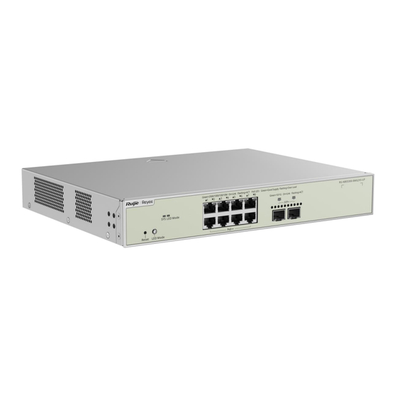
RG-NBS5300 Switches Hardware Installation and Reference Guide Product Introduction Product Introduction Overview 2500/1000/100/10B 10GE/GE SFP+ Console Power Supply Model ase-T Port with Port Port Module Module Auto-Negotiation RG-NBS5300-8M 1 x fixed power G2XS-UP supply module Note SFP+ is backward compatible with SFP. Package Contents Package Contents Table 1-1... -
Page 6: Front Panel
RG-NBS5300 Switches Hardware Installation and Reference Guide Product Introduction Note The package contents above are intended to provide a general overview, and are subject to the terms of the order contract. Please check your goods carefully against the package contents or order contract. If you have any questions, please contact the distributor. - Page 7 Slow blinking green (2 times/s): The system is operating normally, but is not connected to Ruijie Cloud. System LED Solid green: The system is operating normally, and is connected to Ruijie Cloud. Blinking yellow: The system has an alarm due to insufficient total available PoE power.
- Page 8 RG-NBS5300 Switches Hardware Installation and Reference Guide Product Introduction Link/Ack status LED Off: No link is set up on the port. Solid green: The port is operating at 2500 Mpbs/1000 Mpbs/100 Mpbs/10 Mpbs, but is not receiving or sending data. Blinking green: The port is operating at Electrical port 2500Mpbs/1000Mpbs/100Mpbs/10Mpbs, and is receiving or sending data.
-
Page 9: Technical Specifications
Transceiver and Note Cable Types The supported transceiver types may update without prior notification. Please contact Ruijie Networks for any updates. AC input: Rated voltage range: 100 V AC to 240 V AC Max. voltage range: 90 V AC to 264 V AC... - Page 10 RG-NBS5300 Switches Hardware Installation and Reference Guide Product Introduction Press and hold for less than 2 seconds: The system restarts. Press and hold for more than 5 seconds, and then release when the system LED Reset Button starts flashing: The web password is restored to the default value, the system restores to factory defaults and restarts after saving the configuration file.
-
Page 11: Preparation Before Installation
RG-NBS5300 Switches Hardware Installation and Reference Guide Preparation before Installation Preparation before Installation Safety Suggestions To avoid personal injury and device damage, carefully read the safety suggestions before you install the RG-NBS5200 series. The following safety suggestions may not cover all possible dangers. General Safety Precautions 2.1.1 Take security measures (such as wearing an anti-static wrist strap) to ensure safety. - Page 12 RG-NBS5300 Switches Hardware Installation and Reference Guide Preparation before Installation If a power supply system is equipped with a leakage protector (leakage current switch or breaker), the rated leakage action current of each leakage protector is twice greater than the maximum leakage current of all the power supplies in the system.
-
Page 13: Installation Site Requirements
The built-in lithium batteries can support the real time clock of the RG-NBS5300-8MG2XS-UP switch without external power supply. To replace lithium batteries, please contact technical support personnel of Ruijie Networks. The technical support personnel will select lithium batteries of the same specifications for replacement. - Page 14 RG-NBS5300 Switches Hardware Installation and Reference Guide Preparation before Installation If the equipment room has temperature and humidity that do not meet the requirements for a long time, the equipment may be damaged. In an environment with a high humidity, insulating materials may have bad insulation or even leaking ...
- Page 15 RG-NBS5300 Switches Hardware Installation and Reference Guide Preparation before Installation The average and maximum values are measured for a week. The switch cannot be placed in the environment with the maximum density for over 30 minutes every day. Grounding 2.2.6 A good grounding system is the basis for stable and reliable operation of the device, preventing lightning strokes and resisting interference.
-
Page 16: Lightning Resistance
RG-NBS5300 Switches Hardware Installation and Reference Guide Preparation before Installation 2.2.7 Electro-Magnetic Interference (EMI), from either outside or inside the device or application system, affects the system in the conductive ways such as capacitive coupling, inductive coupling, and electromagnetic radiation. There are two types of electromagnetic interference: radiated interference and conducted interference, depending on the type of the transmission path. - Page 17 RG-NBS5300 Switches Hardware Installation and Reference Guide Preparation before Installation 19-inch Cabinet Figure 2-2 Be sure that the square hold strip is at least 125 mm (4.92 in.) far from the outboard front door and the door is at most 25 mm (0.98 in.) thick to ensure a minimum available distance of 100 mm (3.94 in.). The front door is at least 500 mm (19.69 in.) far from the back door.
-
Page 18: Installation Tools
RG-NBS5300 Switches Hardware Installation and Reference Guide Preparation before Installation accessories. Be sure that the cabinet provides a grounding point for the switch to be grounded. Be sure that the front and back doors of the cabinet have porosities greater than 50% for good ... -
Page 19: Product Installation
RG-NBS5300 Switches Hardware Installation and Reference Guide Product Installation Product Installation Installation Flowchart Confirmations Before Installation Before installation, confirm the following points: Check whether ventilation requirements are met for the switch. - Page 20 RG-NBS5300 Switches Hardware Installation and Reference Guide Product Installation Check whether the requirements of temperature and humidity are met for the switch. Check whether power cables are already laid out and whether the requirements of electrical current are met.
- Page 21 RG-NBS5300 Switches Hardware Installation and Reference Guide Product Installation Step 2: Use the supplied M6 screws and cage nuts to securely attach the mounting brackets to the rack.
-
Page 22: Grounding The Switch
RG-NBS5300 Switches Hardware Installation and Reference Guide Product Installation Mounting the Switch on a Table 3.3.2 Attach the four rubber pads to the recessed areas on the bottom of the switch. The device must be installed and operated in the place that can restrict its movement. Grounding the Switch The RG-NBS5300 has a PGND on the back panel. -
Page 23: Bundling Cables
RG-NBS5300 Switches Hardware Installation and Reference Guide Product Installation Step 2: Insert the single-mode or multimode fiber into the appropriate port according to the identification on the panel of the module. Step 3: Insert the twisted pair with the RJ45 connector into the appropriate port according to the identification on the panel of the module. -
Page 24: Checking After Installation
RG-NBS5300 Switches Hardware Installation and Reference Guide Product Installation Checking After Installation Before checking the installation, switch off the power supply so as to avoid any personal injury or damage to the component due to connection errors. Check that the ground line is connected. Check that the cables and power input cables are correctly connected. -
Page 25: System Commissioning
RG-NBS5300 Switches Hardware Installation and Reference Guide System Commissioning System Commissioning Establishing the Configuration Environment Establishing the Configuration Environment Use the network cable to connect a PC to the switch. Figure 4-1 Configuration Environment Connecting the Console Cable Connect the one end (RJ45 port) of the network cable to the network port of the PC. ... - Page 26 RG-NBS5300 Switches Hardware Installation and Reference Guide System Commissioning After power-on, you are advised to perform the following checks to ensure the normal operation of follow-up configurations. Check whether the status of the switch indicator is normal. Check whether the main program is loaded normally. ...
-
Page 27: Troubleshooting Flowchart
RG-NBS5300 Switches Hardware Installation and Reference Guide Troubleshooting Troubleshooting Troubleshooting Flowchart Troubleshooting Common Faults Symptom Possible Causes Solution The management interface login A password is manually Press the reset button to restore the password is configured but it is forgotten. default settings. - Page 28 RG-NBS5300 Switches Hardware Installation and Reference Guide Troubleshooting an error occurs The length of the cable exceeds common working mode with the when the port is 100 m. connected switch. receiving or The port has special transmitting configuration, which does not frames.
-
Page 29: Appendix A Connectors And Connection Media
RG-NBS5300 Switches Hardware Installation and Reference Guide Appendix A Connectors and Connection Media Appendix A Connectors and Connection Media 1000BASE-T/100BASE-TX/10BASE-T Ports The 1000BASE-T/100BASE-TX/10BASE-T supports adaptation of three rates and automatic MDI/MDIX crossover at these three rates. The 1000BASE-T complies with IEEE 802.3ab, and uses the cable of 100-ohm Category-5 or Supper Category-5 UTP or STP, which can be up to 100 m. - Page 30 RG-NBS5300 Switches Hardware Installation and Reference Guide Appendix A Connectors and Connection Media For the optical fiber ports, select single-mode or multimode optical fibers for connection according to the fiber module connected. Figure A-4 shows the connection schematic diagram. Figure A-4 Optical Fiber Connections...
-
Page 31: Appendix B Mini-Gbic And Spf Module
SFP modules (mini-GBIC module) and 10G SFP+ modules are available to cope with interface types of switch modules. You can select the mini-GBIC module to suit your specific needs. The models and technical specifications of some mini-GBIC and 10G SFP+ modules are listed below. For details, see Ruijie Transceiver Installation and Reference Guide. - Page 32 RG-NBS5300 Switches Hardware Installation and Reference Guide Appendix B Mini-GBIC and SPF Module GE-SFP-LH40 1310TX/1 -SM1310-BI 550RX GE-SFP-LH40 1550TX/1 -SM1550-BI 310RX MINI-GBIC-Z 1550 X50-SM1550 MINI-GBIC-Z 1550 X80-SM1550 MINI-GBIC-Z X100-SM155 1550 GE-SFP-SX -9.5 GE-SFP-LX 1310 -9.5 SFP-MM850 -9.5 SFP-SM1310 1310 -9.5 Table B-2 Models and Technical Specifications of the Mini-GBIC-GT Module Standard 1000Base-T SFP Type...
- Page 33 RG-NBS5300 Switches Hardware Installation and Reference Guide Appendix B Mini-GBIC and SPF Module MINI-GBIC-LH40-S 9/125 40 km M1310 GE-SFP-SX-SM1310- 50/125 500 m BIDI GE-SFP-SX-SM1550- 50/125 500 m BIDI GE-SFP-LX20-SM131 9/125 20 km 0-BIDI GE-SFP-LX20-SM155 9/125 20 km 0-BIDI GE-SFP-LH40-SM13 9/125 40 km 10-BIDI GE-SFP-LH40-SM15...
-
Page 34: Appendix C Surge Protection
RG-NBS5300 Switches Hardware Installation and Reference Guide Appendix C Surge Protection Appendix C Surge Protection Installing the AC Power Arrester (Surge Protection Cable Row) The external surge protection cable row must be used on the AC power port to prevent the switch from being struck by lightning when the AC power cable is introduced from the outdoor and directly connected to the power port of the switch. - Page 35 RG-NBS5300 Switches Hardware Installation and Reference Guide Appendix C Surge Protection Tear one side of the protection paper for the double-sided adhesive tape and paste the tape to the framework of the Ethernet port arrester. Tear the other side of the protection paper for the double-sided adhesive tape and paste the Ethernet port arrester to the switch framework.
-
Page 36: Appendix D Cabling Recommendations
RG-NBS5300 Switches Hardware Installation and Reference Guide Appendix D Cabling Recommendations Appendix D Cabling Recommendations When RG-NBS5300 series switches are installed in standard 19-inch cabinets, cables are tied in the binding rack on the cabinet by the cabling rack, and top or bottom cabling is adopted according to the actual situation in the equipment room. - Page 37 RG-NBS5300 Switches Hardware Installation and Reference Guide Appendix D Cabling Recommendations Route and bundle power, signal, ground cables separately. When the cables are close to each other, cross them. When power cables are parallel to signal cables, the distance between them must be 30 mm (1.18 in.).
- Page 38 RG-NBS5300 Switches Hardware Installation and Reference Guide Appendix D Cabling Recommendations length does not contact heat sources, sharp corners, or edges. If heat sources are unavoidable, use high-temperature cables instead. When using screws to fasten cable lugs, the bolts or nuts should be tightened and prevented from loosening, as shown in Figure D-4.
-
Page 39: Appendix E Site Selection
RG-NBS5300 Switches Hardware Installation and Reference Guide Appendix E Site Selection Appendix E Site Selection The equipment room should be at least 5 km away from the heavy pollution source such as the smelter, coal mine, and thermal power plant, 3.7 km away from the medium pollution source such as the chemical industry, rubber industry, and electroplating industry, and 2 km away from the light pollution source such as the food manufacturer and leather plant.
Need help?
Do you have a question about the Reyee RG-NBS5300-8MG2XS-UP Series and is the answer not in the manual?
Questions and answers