
Related Manuals for Ruijie Reyee RG-NBS5200-48GT4XS-UP


Summary of Contents for Ruijie Reyee RG-NBS5200-48GT4XS-UP
- Page 1 RG-NBS5200-48GT4XS-UP Switch Hardware Installation and Reference Guide Document Version: V1.0 Date: June 01, 2023 Copyright © 2023 Ruijie Networks...
-
Page 2: Product Overview
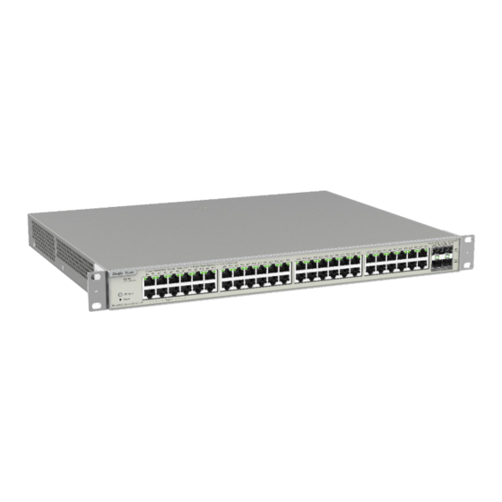
The RG-NBS5200-48GT4XS-UP switch provides 48 10/100/1000Base-T RJ45 Ethernet ports and four 10GE SFP+ ports on the front panel, and an AC connector on the rear panel. The switch supports routing, Rapid Spanning Tree Protocol (RSTP) and link aggregation. It can be managed through Eweb, Ruijie Cloud and App. Package Contents... -
Page 3: Front Panel
Hardware Installation and Reference Guide Product Overview Item Quantity M4 x 8 mm Screw M6 Cage Nut Management Software Grounding Cable Power Cord (1.8 m/5.91 ft) Power Cord Retention Clip User Manual Warranty Card Note The above is the general Packet Contents. The actual delivery is subject to the order contract. And please check your goods carefully against the order contract. -
Page 4: Rear Panel
System Status Ruijie Cloud, Fast blinking (10 Hz): The switch is upgrading or restarting. Solid green: The switch is operating properly and connected to Ruijie Cloud. Off: The LED indicates the Link/ACK status. LED Mode LED Solid green: The LED indicates the PoE status. - Page 5 Hardware Installation and Reference Guide Product Overview Table 1-3 Ports and Buttons on the Rear panel Item Description AC Connector Connect to an external AC power supply. Power Cord Secure the power cord. Retention Clip Secure the grounding lug to ensure connection between the chassis and earth Grounding Screw ground.
-
Page 6: Technical Specifications
Hardware Installation and Reference Guide Product Overview Technical Specifications Table 1-4 Specifications Model RG-NBS5200-48GT4XS-UP 1 GHz dual-core CPU Flash Memory 256 MB SDRAM DDRIII 512 MB 48 10/100/1000Base-T Ethernet ports with auto negotiation and crossover detection (auto MDI/MDIX crossover) Ports 1 to 48 are PoE-capable Four 10GE SFP+ ports Port Note... -
Page 7: Preparing For Installation
Hardware Installation and Reference Guide Preparing for Installation Operating Altitude 0 m to 5000 m (0 to 16404 ft) Operating Temperature 0° C to 50° C (32° F to 122° F) –40º C to 70º C (–40° F to 158° F) Storage Temperature Operating Humidity 10% to 90% RH (non-condensing) -
Page 8: Handling Safety
Hardware Installation and Reference Guide Preparing for Installation hooked by the chassis. Keep tools and components away from walking areas. 2.1.2 Handling Safety Prevent the switch from being frequently handled. Cut off all power supplies and unplug all power cords before moving or handling the device. ... -
Page 9: Installation Environment Requirements
Hardware Installation and Reference Guide Preparing for Installation Caution ● To guarantee personal safety, the rated leakage action current of each leakage protector in the system must be equal to or less than 30 mA (human body safety current is 30 mA). When twice of the total leakage current of the system is greater than 30 mA, the system must be equipped with two or more leakage protectors. -
Page 10: Space Requirements
Hardware Installation and Reference Guide Preparing for Installation air inlets. You are advised to dust the switch at an interval of three months to avoid blocking the ventilation openings. 2.2.3 Space Requirements To have sufficient room for chassis handling and module swapping, you are advised to maintain an indoor pathway of at least 800 mm (31.50 in.) wide. -
Page 11: Grounding Requirements
Hardware Installation and Reference Guide Preparing for Installation be properly protected against the intrusion of harmful gases, such as sulfur dioxide, hydrogen sulfide, nitrogen dioxide, and chlorine gas. The following table lists limit values for harmful gases. Table 2-2 Requirements for Gases Average (mg/m Maximum (mg/m Sulfur dioxide (SO... - Page 12 Hardware Installation and Reference Guide Preparing for Installation grounding and safety grounding of the rack. Lightning grounding is required only for facilities and is not required for the switch. Note For lightning protection, please see Section 6.3 Lightning Protection. EMC Grounding Grounding required for electromagnetic compatibility includes shielded grounding, filter grounding, noise and interference suppression, and level reference.
-
Page 13: Installation Site Requirements
Hardware Installation and Reference Guide Preparing for Installation 2.2.9 Installation Site Requirements Regardless of whether the device is installed in a rack or on a workbench, observe the fol lowing conditions: Maintain a proper clearance around the air intakes and outlets for heat dissipation. ... - Page 14 Hardware Installation and Reference Guide Preparing for Installation Tools Table 2-3 Tools Common Phillips screwdriver, power cords, Ethernet cables, fastening bolts, diagonal plier and cable Tools ties Anti-static wrist strap, wire stripper, crimping plier, crystal connector crimping plier, and wire Special Tools cutter Meters...
-
Page 15: Installing The Switch
Hardware Installation and Reference Guide Installing the Switch Installing the Switch Caution Before installing the switch, make sure that you have carefully read and met the requirements specified in Chapter 2. Installation Flowchart Install the switch Ground the switch Connect the power supply Connect the cables Bundle the cables Verify the installation... -
Page 16: Before You Begin
Hardware Installation and Reference Guide Installing the Switch Before You Begin The installation site provides sufficient space for heat dissipation. The installation site meets the temperature and humidity requirem ents of the switch. The power supply is available in the installation site and meets requirement for current. ... - Page 17 Hardware Installation and Reference Guide Installing the Switch Figure 3-1 Securing Mounting Brackets Step 2: Use M6 screws and cage nuts to secure the other end of the mounting brackets to square hole rack posts. Figure 3-2 Installing Cage Nuts and Screws...
-
Page 18: Installing The Switch On A Workbench
Hardware Installation and Reference Guide Installing the Switch Figure 3-3 Tightening Screws 3.3.2 Installing the Switch on a Workbench Step 1: Attach the four rubber feet to the four corners at the bottom of the switch. Figure 3-4 Attaching Rubber Feet to the Bottom of the Switch Step 2: Place the switch on a workbench and ensure adequate airflow around the switch. -
Page 19: Connecting The Switch To Earth Ground
Hardware Installation and Reference Guide Installing the Switch Figure 3-5 Installing the Switch on a Workbench Note The location where the switch is installed must be subject to movement restrictions. Connecting the Switch to Earth Ground The switch has a grounding stud on the rear panel. Connect the grounding stud to the grounding lug of the rack and then connect the grounding lug of the rack to the ground buss bar of the machine room. -
Page 20: Bundling Cables
Hardware Installation and Reference Guide Installing the Switch Precautions Make sure that the models of optical transceivers and optical cables match with SFP ports. The transmitting port on the local device should be connected to the receiving port on the peer device and vice versa. ... - Page 21 Hardware Installation and Reference Guide Verifying Operating Status Verifying Operating Status Setting up Configuration Environment Connect the PC to the management port of the switch with an Ethernet cable. Figure 4-1 Configuring Environment Connecting an Ethernet Cable Plug the crystal head of the Ethernet cable into the network port of the PC. Connect the RJ-45 end to any port of the switch.
- Page 22 Hardware Installation and Reference Guide Verifying Operating Status The main program is loaded properly. Service ports can forward data properly.
-
Page 23: Common Troubleshooting
The device is not working properly Check the device installation Check the power connection Check the LEDs on the device Check the cable connection Contact Technical Support of Ruijie Networks Common Faults Symptom Possible Cause Suggested Action Press and hold the Reset button for over five... - Page 24 Hardware Installation and Reference Guide Common Troubleshooting The port is specially configured mode as the interconnected switch. and does not use the same work mode as the interconnected switch. The receiving and transmitting ends are connected incorrectly. Exchange the transmission and receiving The types of the interconnected ends of the optical fiber.
- Page 25 Hardware Installation and Reference Guide...
Need help?
Do you have a question about the Reyee RG-NBS5200-48GT4XS-UP and is the answer not in the manual?
Questions and answers