Ruijie Reyee RG-NBS5100-24GT4SFP Series Installation Manual
Hide thumbs
Also See for Reyee RG-NBS5100-24GT4SFP Series:
- Hardware installation and reference manual (40 pages) ,
- Configuration manual (297 pages)

Subscribe to Our Youtube Channel
Related Manuals for Ruijie Reyee RG-NBS5100-24GT4SFP Series


Summary of Contents for Ruijie Reyee RG-NBS5100-24GT4SFP Series
- Page 1 Ruijie Reyee RG-NBS5100-24GT4SFP, RG-NBS5100-48GT4SFP Series Switches Installation Guide Document Version: V1.3 Date: May 20, 2024 Copyright © 2024 Ruijie Networks...
- Page 2 Ruijie Networks reserves the right to modify the content of the document without any notice or prompt. This manual is designed merely as a user guide. Ruijie Networks has tried its best to ensure the accuracy and reliability of the content when compiling this manual, but it does not guarantee that the content of the manual is completely free of errors or omissions, and all the information in this manual does not constitute any explicit or implicit warranties.
-
Page 3: Preface
Intended Audience This document is intended for: Network engineers Technical support and servicing engineers Network administrators Technical Support The official website of Ruijie Reyee: https://reyee.ruijie.com Technical Support Website: https://reyee.ruijie.com/en-global/support Case Portal: https://www.ruijienetworks.com/support/caseportal Community: https://community.ruijienetworks.com... - Page 4 Note This manual provides installation steps, troubleshooting, technical specifications, and usage guidelines for cables and connectors. It is intended for users who want to understand the above and have extensive experience in network deployment and management, and assume that users are familiar with related terms and concepts.
-
Page 5: Table Of Contents
Contents Preface ..............................I 1 Product Overview ..........................1 1.1 RG-NBS5100-24GT4SFP ......................1 1.2 RG-NBS5100-48GT4SFP ......................4 2 Preparation Before Installation ......................9 2.1 Safety Suggestions ........................9 2.1.1 Installation ........................9 2.1.2 Movement ........................9 2.1.3 Electricity ........................9 2.1.4 ESD .......................... - Page 6 3.2 Confirmations Before Installation ..................... 16 3.3 Installing the RG-NBS5100...................... 17 3.3.1 Mounting the Switch to a Standard 19-inch Rack ............17 3.3.2 Mounting the Switch on a Table ................... 18 3.4 Grounding the Switch ......................19 3.5 Connecting External Cables ....................20 3.6 Bundling Cables ........................
-
Page 7: Product Overview
Product Overview Product Overview Ruijie RG-NBS5100 series switches are mainly applied to the small- and medium-sized enterprise (SME) networks to provide services according to service requirements to ensure transmission of key data. The RG-NBS5100 series switches provide various interfaces to meet different network construction scenarios. - Page 8 Installation Guide Product Overview Rated current: 1.5 A Input Leakage ≤ 3.5 mA Current Supported Not supported Power 28 W Consumption Operating temperature: 0° C to 50° C (32° F to +122° F) Temperature Storage temperature: -40° C to +70° C (-40° F to +158° F) Operating humidity: 10% to 90% RH Humidity Storage humidity: 5% to 95% RH...
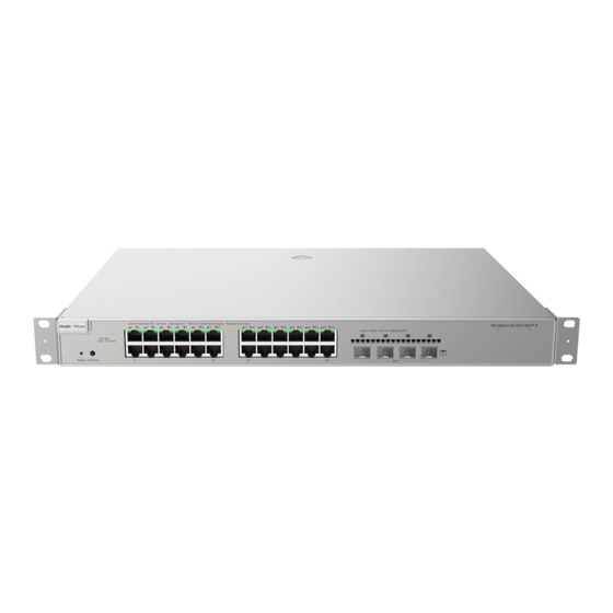
- Page 9 Installation Guide Product Overview Front Panel Figure 1-2 Front Panel of the RG-NBS5100-24GT4SFP Note: 1. Reset button 3. 10/100/1000 Base-T Ethernet port 2. System status LED 4. 1000Base-X SFP port 5. Nameplate on the bottom of the device Note The switch restarts after the reset button is pressed for less than 2 seconds.
-
Page 10: Rg-Nbs5100-48Gt4Sfp
Status Blinking green The switch is being upgraded or (10 Hz) initialized. Solid green The switch is connected to Ruijie Cloud. The port is not connected. 10/100/1000Base-T The port is connected at a rate of Solid green Ethernet port status 1–24... - Page 11 SDRAM DDRIII 1 GB The copper cable is not supported. See Appendix B. Note Optical Module The supported module type may change at any time. Consult Ruijie Networks for the latest information. SFP Port 1000Base-X AC input Rated voltage range: 100 V to 240 V...
- Page 12 Installation Guide Product Overview Caution Device operation in a residential environment may cause radio interference. The device is not suitable for use in locations where children are likely to be present. Product Appearance On the front panel, the RG-NBS5100-48GT4SFP Ethernet switch provides forty-eight 10/100/1000Base-T Ethernet ports and four SFP ports.
- Page 13 When you install devices, reserve 1 RU (44.45 cm) distance space between neighboring devices to allow airflow. Panel State Meaning Identification The switch is not receiving power. Blinking green The switch is running, but is not System status LED Status connected to Ruijie Cloud. (0.5 Hz) Blinking green The switch is being upgraded or...
- Page 14 Product Overview Panel State Meaning Identification (10 Hz) initialized. Solid green The switch is connected to Ruijie Cloud. The port is not connected. 10/100/1000Base-T The port is connected at a rate of Solid green Ethernet port status 1–48 10/100/1000 Mbps.
-
Page 15: Preparation Before Installation
Installation Guide Preparation Before Installation Preparation Before Installation Safety Suggestions To avoid personal injury and device damage, carefully read the safety suggestions before you install the RG-NBS5100 series. Caution The following safety suggestions may not cover all possible dangers. 2.1.1 Installation ... -
Page 16: Esd
Installation Guide Preparation Before Installation supplies, the leakage current of each power supply is equal to or less than 1.5 mA, and the total leakage current of the system is 30 mA. A leakage protector with 30 mA rated action current supports less than ten power supplies (that is, action current of the leakage protector/2/maximum leakage current of each power supply = 30/2/1.5 = 10). -
Page 17: Battery
The switch has a built-in lithium battery to keep the real-time clock running when external power source is unavailable. To replace the lithium battery, please contact Ruijie Networks Customer Service Technical Support to have it replaced with a lithium battery of the same specifications. -
Page 18: Cleanness
Installation Guide Preparation Before Installation 0° C to 50° C (32° F to 122° F) 10% to 90% The requirements for the sampling site of the temperature and humidity in the operating environment of the device are as follows: Caution ... -
Page 19: Interference Resistance
Installation Guide Preparation Before Installation 2.2.4 Interference Resistance The switch is vulnerable to external interface caused by capacity coupling, inductance coupling, electromagnetic wave radiation, common impedance (including grounding system) coupling, and conducting wires (including power cords, signal and output wires). Therefore, note the following points: ... -
Page 20: Lightning Resistance
Installation Guide Preparation Before Installation EMC Grounding The grounding required for EMC design includes the shielding ground, filter ground, noise and interference suppression, and level reference. All the above constitute the comprehensive grounding requirements. The resistance of earth wires should be less than 1 Ω. The RG-NBS5100 series switch back plane is reserved with one grounding pole, as shown in Figure 2-1. -
Page 21: Installation Tools
Installation Guide Preparation Before Installation Do not use the grounding device for an electrical device or anti-lightning grounding device. In addition, the grounding device of the device must be deployed far away from the grounding device of the electrical device and anti-lightning grounding device. -
Page 22: Product Installation
Installation Guide Product Installation Product Installation Installation Flowchart Confirmations Before Installation Before installation, confirm the following points: Check whether ventilation requirements are met for the switch. Check whether the requirements of temperature and humidity are met for the switch. -
Page 23: Installing The Rg-Nbs5100
Installation Guide Product Installation Check whether power cables are already laid out and whether the requirements of electrical current are met. Check whether related network adaption lines are already laid out. Installing the RG-NBS5100 Precautions During installation, note the following points: ... -
Page 24: Mounting The Switch On A Table
Installation Guide Product Installation Figure 3-3 Attaching the Brackets to the Rack 3.3.2 Mounting the Switch on a Table Attach the four rubber pads to the recessed areas on the bottom of the switch, as shown in Figure 3-4 and Figure 3-5. -
Page 25: Grounding The Switch
Installation Guide Product Installation Place the switch on the table, as shown in Figure 3-5. Figure 3-5 Mounting the Switch on the Table Caution The device must be installed and operated in the place that can restrict its movement. Grounding the Switch The RG-NBS5100 has a PGND on the back panel. -
Page 26: Connecting External Cables
Installation Guide Product Installation Caution To guarantee the security of the body and the device, the switch must be well-grounded. The grounding resistance for combined grounding should be less than 1 Ω. The maintenance personnel must check whether the AC socket powering the switch is well connected to the building protective earth (PE). -
Page 27: Checking After Installation
Installation Guide Product Installation Checking After Installation Caution Before checking the installation, switch off the power supply so as to avoid any personal injury or damage to the component due to connection errors. Check that the ground line is connected. ... -
Page 28: System Commissioning
Installation Guide System Commissioning System Commissioning Establishing the Configuration Environment Establishing the Configuration Environment Use the network cable to connect a PC to the switch. Figure 4-1 Configuration Environment Connecting the Console Cable Connect the one end (RJ45 port) of the network cable to the network port of the PC. ... - Page 29 Installation Guide System Commissioning The console cable is correctly connected; the PC is already started; parameters are configured. Checking After Power-on (Recommended) After power-on, you are advised to perform the following checks to ensure the normal operation of follow-up configurations.
-
Page 30: Troubleshooting
Installation Guide Troubleshooting Troubleshooting Troubleshooting Flowchart Troubleshooting Common Faults Symptom Possible Causes Solution The management interface login A password is manually configured Press the reset button to restore the default password is but it is forgotten. settings. forgotten. Check whether the power socket is normal. The status LED is The power supply is not enabled, Check whether the power cable is correctly... - Page 31 Installation Guide Troubleshooting frames. which does not adapt to the working mode of the connected switch. Switch the Rx and Tx ends of the optical The Rx and Tx ends are module. connected reversely. Replace the optical module with one of the The interconnected optical module The optical port matched type.
-
Page 32: Appendix
Installation Guide Appendix Appendix Appendix A Connectors and Connection Media 1000BASE-T/100BASE-TX/10BASE-T Ports The 1000BASE-T/100BASE-TX/10BASE-T supports adaptation of three rates and automatic MDI/MDIX crossover at these three rates. The 1000BASE-T complies with IEEE 802.3ab, and uses the cable of 100-ohm Category-5 or Supper Category-5 UTP or STP, which can be up to 100 m. - Page 33 Installation Guide Appendix Optical Fiber Connection For the optical fiber ports, select single-mode or multimode optical fibers for connection according to the fiber module connected. Figure A-4 shows the connection schematic diagram. Figure A-4 Optical Fiber Connection...
-
Page 34: Appendix B Mini-Gbic Module
SFP modules (mini-GBIC module) and 10G SFP+ modules are available to cope with interface types of switch modules. You can select the mini-GBIC module to suit your specific needs. The models and technical specifications of some mini-GBIC and 10G SFP+ modules are listed below. For details, see Ruijie Transceiver Installation and Reference Guide. - Page 35 Installation Guide Appendix M1550-BIDI MINI-GBIC-ZX50 1550 -SM1550 MINI-GBIC-ZX80 1550 -SM1550 MINI-GBIC-ZX10 1550 0-SM1550 GE-SFP-SX -9.5 GE-SFP-LX 1310 -9.5 SFP-MM850 -9.5 SFP-SM1310 1310 -9.5 Table B-2 Models and Technical Specifications of the Mini-GBIC-GT Module Standard 1000Base-T SFP Type DDM (Yes/No) 1000Base-T Mini-GBIC-GT Table B-3 Cabling Specifications of SFP Modules Maximum...
- Page 36 Installation Guide Appendix GE-SFP-LX20-SM1310- 9/125 20 km BIDI GE-SFP-LX20-SM1550- 9/125 20 km BIDI GE-SFP-LH40-SM1310- 9/125 40 km BIDI GE-SFP-LH40-SM1550- 9/125 40 km BIDI MINI-GBIC-ZX50-SM155 9/125 50 km MINI-GBIC-ZX80-SM155 9/125 80 km MINI-GBIC-ZX100-SM15 9/125 100 km 62.5/125 275 m GE-SFP-SX 50/125 550 m GE-SFP-LX 9/125...
- Page 37 Installation Guide Appendix Caution The BIDI modules must be used in pairs, for example, FE-SFP-LX20-SM1310-BIDI and FE-SFP-LX20-SM1550-BIDI are used together.
-
Page 38: Appendix C Surge Protection
Installation Guide Appendix Appendix C Surge Protection Installing the AC Power Arrester (Surge Protection Cable Row) The external surge protection cable row must be used on the AC power port to prevent the switch from being struck by lightning when the AC power cable is introduced from the outdoor and directly connected to the power port of the switch. - Page 39 Installation Guide Appendix (1) Tear one side of the protection paper for the double-sided adhesive tape and paste the tape to the framework of the Ethernet port arrester. Tear the other side of the protection paper for the double-sided adhesive tape and paste the Ethernet port arrester to the switch framework. The paste location for the Ethernet port arrester must be as close to the grounding terminal of the switch.
-
Page 40: Appendix D Cabling Recommendations
Installation Guide Appendix Appendix D Cabling Recommendations When RG-NBS5100 series switches are installed in standard 19-inch cabinets, cables are tied in the binding rack on the cabinet by the cabling rack, and top or bottom cabling is adopted according to the actual situation in the equipment room. - Page 41 Installation Guide Appendix Route and bundle power, signal, ground cables separately. When the cables are close to each other, cross them. When power cables are parallel to signal cables, the distance between them must be 30 mm (1.18 in.). ...
- Page 42 Installation Guide Appendix Leave a specified length of the cable connecting moving parts, such as the ground wire of the cabinet door, to avoid stress on the cable. When moving parts are in place, ensure that the excess cable length does not contact heat sources, sharp corners, or edges.
-
Page 43: Appendix E Site Selection
Installation Guide Appendix Appendix E Site Selection The equipment room should be at least 5 km away from the heavy pollution source such as the smelter, coal mine, and thermal power plant, 3.7 km away from the medium pollution source such as the chemical industry, rubber industry, and electroplating industry, and 2 km away from the light pollution source such as the food manufacturer and leather plant.
Need help?
Do you have a question about the Reyee RG-NBS5100-24GT4SFP Series and is the answer not in the manual?
Questions and answers