
Related Manuals for Directed Electronics 554R


Summary of Contents for Directed Electronics 554R
- Page 1 M M o o d d e e l l 5 5 5 5 4 4 RT O O w w n n e e r r ’ ’ s s G G u u i i d d e e...
-
Page 2: L L I I M M I I T T E E D D L L I I F F E E T T I I M M E E C C O O N N S S U U M M E E R R W W A A R R R R A A N N T T Y Y
l l i i m m i i t t e e d d l l i i f f e e t t i i m m e e c c o o n n s s u u m m e e r r w w a a r r r r a a n n t t y y Directed Electronics, Inc. - Page 3 CONSEQUENTIAL DAMAGES OF ANY KIND. IN THE EVENT OF A CLAIM OR A DISPUTE INVOLVING DIRECTED OR ITS SUBSIDIARY, THE PROPER VENUE SHALL BE SAN DIEGO COUNTY IN THE STATE OF CALIFORNIA. CALIFORNIA STATE LAWS AND APPLICABLE FEDERAL LAWS SHALL APPLY AND GOVERN THE DISPUTE.
-
Page 4: Table Of Contents
t t a a b b l l e e o o f f c c o o n n t t e e n n t t s s l l i i m m i i t t e e d d l l i i f f e e t t i i m m e e c c o o n n s s u u m m e e r r w w a a r r r r a a n n t t y y ..i i t t r r a a n n s s c c e e i i v v e e r r d d i i a a g g r r a a m m . - Page 5 t t r r a a n n s s c c e e i i v v e e r r d d i i a a g g r r a a m m © 2003 directed electronics, inc.
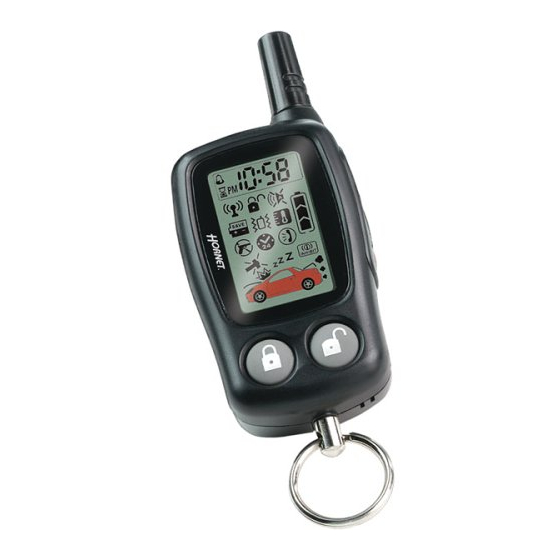
- Page 6 s s t t a a n n d d a a r r d d t t r r a a n n s s c c e e i i v v e e r r c c o o n n f f i i g g u u r r a a t t i i o o n n s s Vehicle Interior Temperature Indicator Numeric Display AM/PM Indicator...
-
Page 7: Control Module
w w h h a a t t i i s s i i n n c c l l u u d d e e d d Control module A.S.K. Receiver One four-button two-way transceiver One four-button transmitter Stinger™ DoubleGuard® two-stage shock sensor Revenger™... -
Page 8: Warning! Safety First
warning! safety first The following safety warnings must be observed at all times: warning! THIS SYSTEM PROVIDES REMOTE NOTI- FICATION OF SECURITY SYSTEM TRIGGER EVENTS. CONTACT POLICE OR SECURITY PER- SONNEL IMMEDIATELY. NEVER CONFRONT A CAR THIEF OR VANDAL. Due to the complexity of this system, installation of this product must only be performed by an authorized Directed dealer. - Page 9 Use of this product in a manner contrary to its intended mode of operation may result in property damage, personal injury, or death. (1) Never remotely start the vehicle with the vehicle in gear, and (2) Never remotely start the vehicle with the keys in the ignition.
-
Page 10: System Maintenance
D D I I A A T T E E L L Y Y C C E E A A S S E E T T H H E E U U S S E E O O F F T T H H E E U U N N I I T T A A N N D D S S E E E E K K T T H H E E A A S S S S I I S S T T A A N N C C E E O O F F A A N N A A U U T T H H O O R R I I Z Z E E D D D D I I R R E E C C T T E E D D D D E E A A L L E E R R T T O O R R E E P P A A I I R R O O R R D D I I S S C C O O N N N N E E C C T T T T H H E E I I N N S S T T A A L L L L E E D D R R E E M M O O T T E E S S T T A A R R T T M M O O D D U U L L E E . -
Page 11: Your Warranty
your warranty Your warranty registration must be completely filled out and returned within 10 days of purchase. Your product warranty will not be validated if your warranty registration is not returned. Make sure you receive the warranty registration from your dealer. It is also necessary to keep your proof of purchase, which reflects that the product was installed by an authorized dealer. -
Page 12: Caution
caution This product is designed for fuel-injected, automatic transmis- sion vehicles only. Use of this product in a standard transmission vehicle is dangerous and contrary the product's intended use. t t r r a a n n s s c c e e i i v v e e r r f f u u n n c c t t i i o o n n s s The transceiver buttons are used to send commands to the system. - Page 13 Button The LCD backlighting will turn on when pressed for less than one second; when held for more than five seconds the transceiver will enter adjustment mode allowing the setting of the clock, timer mode, and audible melody selection. For more information, please refer to the Function Button Configurations section of this guide.
-
Page 14: Standard Icon Configurations
Buttons Press these buttons simultaneously to activate the parking timer. Each additional press will toggle through the available options (10 min., 20 min., 30 min., 1 hour, 1.5 hours, 2 hours, and off ). Buttons When pressed simultaneously these buttons toggle between beep notification and vibrate notification. - Page 15 Icon The timer function icon flashes during timed functions including parking timer. Icon The transmit range indicator icon stays visible as long as the system is within operating range. Icon The remote transmission indicator icon displays when the trans- ceiver is transmitting a signal. Icon The vibrate/beep mode icon appears when the transceiver is set to vibrate mode.
- Page 16 Icon The full trigger shock sensor icon indicates that the shock sensor has been triggered by a hard shock. Icons The hood/trunk open or trigger icon illuminates when the hood or trunk trigger has been activated or the hood or trunk is open, and bypasses those zones until it is closed.
- Page 17 Icon The battery level icon indicates the level of power remaining in the battery. Icon The temperature-controlled remote start icon indicates that the system has entered the temperature remote start mode and auto- matically starts the vehicle if the temperature of the vehicle drops below 0 degrees Fahrenheit.
-
Page 18: Function Button Configurations
function button configurations F F u u n n c c t t i i o o n n B B u u t t t t o o n n Lamp On (10 sec) Power-Saver Mode* Beep/Vibrate Mode Time Adjust for 5 Seconds Mode (hour)** Time Adjust... - Page 19 Remote Start On 10 times*** Melody Selection 2 10 Min Parking Count Down Mode 20 Min Parking Count Down Mode 30 Min Parking Count Down Mode 60 Min Parking Count Down Mode 90 Min Parking Count Down Mode 120 Min Parking Count Down Mode Parking Count Down Off Mode...
-
Page 20: System Signal Paging Features
r r e e m m o o t t e e o o p p e e r r a a t t i i o o n n The 554 remote start system operates at 434 MHz and incorpo- rates Directed’s proprietary A.S.K. -
Page 21: Active Arming
u u s s i i n n g g y y o o u u r r s s y y s s t t e e m m active arming Press for one second to arm the system. The vehicle’s lights will flash once, the doors will lock, the siren will chirp once, and while the system is armed, the status LED will blink approxi- mately once per second to indicate the system is actively... -
Page 22: Vehicle Protection
3. The status LED will blink at twice its normal rate indicating the system has begun the 30 second countdown. 4. After 20 seconds the siren will chirp once (unless programmed off ) as an audible indication that the system is about to arm. -
Page 23: Warn Away Response Description
W W a a r r n n A A w w a a y y ® ® - Light impacts trigger the Warn Away When triggered, the siren chirps and the parking lights flash for a few seconds. T T r r i i g g g g e e r r e e d d S S e e q q u u e e n n c c e e - Heavy impacts trip a Triggered Sequence. -
Page 24: Triggered Response Description
note: Icons 13 and 14 represent alarm system zone inputs. For more information about icons and the zones they represent refer to the Standard Remote Configurations section. triggered response description A Triggered Response can be activated by any of the triggers listed below and consists of an alarm page along with the response described for each trigger. -
Page 25: Arming/Disarming While Driving
When a Triggered Response is activated the transceiver will: Repeat four quick beeps (or vibrate) for 15 seconds. The full trigger alert icon (28) will turn on for 15 seconds The zone icons will turn on and remain on until a transceiver button is pressed, clearing the page alert. -
Page 26: Multi-Level Security Arming
Disarming while driving Press on the transceiver or simply turn off the ignition to disarm the system. The lights will flash twice, the doors will unlock, the siren will chirp twice, and the status LED will turn off. The transceiver will beep twice (or vibrate). The disarm icon (29) will be displayed on the LCD. -
Page 27: Disarming
Press a fourth time within five seconds: The siren chirps four times followed by a long chirp. Zones 2 and 4 are now bypassed. Press a fifth time within five seconds: The siren chirps five times followed by a long chirp. All input zones, except the ignition, are now bypassed. -
Page 28: High Security Disarm
high security disarm This security system offers High Security Disarm. High Security Disarm is a feature that makes it possible to silence and reset the system while it is triggered, without disarming the system. If the system is triggered and the siren has been sounding for longer than six seconds, press any button on the transceiver to stop the page, then press on the transceiver to stop the trigger and... -
Page 29: Disarming Without A Transceiver
disarming without a transceiver (emergency override) If your transceiver is lost or damaged, you can manually disarm your vehicle security system. To disarm the system without a transceiver, you must have the vehicle's ignition key and know where the Valet switch is located. -
Page 30: Panic Mode
arming or disarming, and the confirmation chirp(s) will be elim- inated for that one operation only. When Silent Mode has been used the silent arm/disarm mode icon will indicate silent arm/disarm. If you want the arm/disarm chirps turned off permanently, your dealer can do this for you. note: The Warn Away bypassed if the system is armed using Silent Mode. -
Page 31: Valet Mode
valet mode You can prevent your security system from passive arming by using Valet mode. This is very useful when washing the vehicle or having it serviced. In Valet mode, the security system will not arm, even with the transceiver, but all convenience functions (door locks, trunk release, remote starting, etc.) will continue to work normally. -
Page 32: Remote Start
buttons are used when entering and exiting valet mode. The status LED is the only way to ensure the system has entered/exited valet mode. remote start This feature allows you to remotely start and run your vehicle for a programmable period of time. This makes it possible to warm up the engine, as well as adjust the interior temperature of the vehicle with the climate control system. - Page 33 4. In gasoline vehicles, the engine will start four seconds after the parking lights flash. In diesel vehicles, the engine will start when the WAIT-TO-START indicator on the vehicle's dash goes out. 5. Once the vehicle has started, it will run for the pre-program- med period of time (either 12, 24, or 60 minutes - see Programming Options section of this guide) or until a shut- down input is triggered.
-
Page 34: Valet Take-Over
The hood is opened. The shutdown toggle switch is put into the OFF position. The pre-programmed run time (12, 24, or 60 minutes) has elapsed. Transceiver buttons the vehicle. The transceiver will generate a page notification with a unique melody (or vibrate) and the remote start icon (19) will turn off when the remote start shuts down. -
Page 35: Setting The Clock
3. The engine will run until the pre-programmed time elapses or a shut-down input is received. (See the previous Remote Start section for a complete list of shut-down inputs.) note: This feature will not work if the brake pedal is pressed or if any shut down input is active. -
Page 36: Starter Anti-Grind Circuitry
s s a a f f e e t t y y f f e e a a t t u u r r e e s s This system has several important safety features to ensure proper operation of the motor and prevent accidental damage to the engine or its components. -
Page 37: Over And Under Rev Protection
over and under rev protection The system monitors the engine speed and will automatically shut the engine off if the RPMs rise above or fall below the programmed levels. This feature prevents damage to the motor due to fuel delivery system failures or other problems which may cause the engine to race. - Page 38 Example If the alarm triggers three times within a 60-minute period and each time the same sensor or switch triggers the alarm, NPC will interpret those triggers as false alarms. After the third trigger, ignores, or bypasses, that sensor or switch (along with any ™...
-
Page 39: Arming Diagnostics
d d i i a a g g n n o o s s t t i i c c s s The microprocessor at the heart of your system is constantly monitoring all of the switches and sensors connected to it. It is designed to detect any faulty switches and sensors and prevents them from disabling the entire system. -
Page 40: System Status Chirps
triggered so many times that the Nuisance Protection Circuitry has bypassed that zone. In either case, the status LED and trans- ceiver LCD will indicate which zone was triggered (see Table of Zones section). The security system will retain this information in its memory and chirp four or five times each time it is dis- armed, until the next time that the ignition is turned on. -
Page 41: Table Of Zones
table of zones A zone is represented by the LED flashes used by the system to identify a particular type of input. Standard input assignments are listed in the following table. ZONE (Number of DESCRIPTION LED Flashes) Instant trigger - hood pinswitch Instant trigger - a heavier impact detected by the shock sensor Door switch trigger Instant trigger - for optional sensors... - Page 42 note: Your system stores the last two triggered zones in memory. If your system has been triggered but the LED has been reset by turning on the ignition, your dealer can still recall the last two zones that were triggered. Contact your dealer for details.
- Page 43 c c o o d d e e h h o o p p p p i i n n g g The receiver and transmitters use a mathematical formula called an algorithm to change their code each time the transceiver is used.
- Page 44 vehicle, one for each user. note: Owner Recognition cannot be programmed with- out a Bitwriter and the necessary software. Check with your dealer for more information. r r a a p p i i d d r r e e s s u u m m e e l l o o g g i i c c This Directed system will store its current state to non-volatile memory.
- Page 45 Power Saver in Valet ® Mode the LED illuminates steadily. If the vehicle is not used (ignition is not turned on) for a one hour period while the system is in Valet Mode, the LED will shut off. If the ®...
- Page 46 locking allows the vehicle's doors to lock when the security system passively arms (after the 30-second countdown). This feature only works if passive arming has been programmed. Panic mode e e n n a a b b l l e e d d /disabled when the ignition is turned on.
- Page 47 times, regardless of whether or not the alarm is armed. If AED is programmed on, the starter of the vehicle will be disabled 30 seconds after the ignition is turned off. Once the key is turned off, the LED will flash slowly (one-half its normal armed rate) to indicate the AED arming cycle.
- Page 48 s s e e c c u u r r i i t t y y & & c c o o n n v v e e n n i i e e n n c c e e e e x x p p a a n n - - s s i i o o n n s s Listed below are some of the many expansion options available.
- Page 49 The accessory output of the system can op- Power Trunk Release: erate a factory power release for the vehicle’s trunk or hatch. Although the on-board relay can control most power trunk re- leases, sometimes an optional relay is required. If the factory release is not power-activated, Directed solenoid can often be added.
- Page 50 circuitry for the starter interrupt, however installation may require additional labor. A physical connection to the system. An input can be Input: provided by a sensor, pinswitch or by existing systems in the vehicle, such as ignition or courtesy lights. A red light mounted at a discretionary location inside the LED: vehicle.
- Page 51 Valet Mode and for programming when the 998T Bitwriter is not available. Lighter impacts to the vehicle will generate Warn Away Response: the Warn Away response. It consists of several seconds of siren chirps and parking light flashes. A zone is a separate input that the alarm can recognize as Zone: unique.
- Page 52 © 2003 directed electronics, inc.
- Page 53 The company behind this system is Directed Electronics, Inc. Since its inception, Directed Electronics has had one purpose, to provide consumers with the finest vehicle security and car stereo products and accessories available. The recipient of nearly 100 patents and Innovations Awards in the field of advanced electronic technology, Directed is ISO 9001 registered.
Need help?
Do you have a question about the 554R and is the answer not in the manual?
Questions and answers