
Subscribe to Our Youtube Channel
Related Manuals for D-Link DE-1824EI


Summary of Contents for D-Link DE-1824EI
- Page 1 10BASE-T Stackable Hubs Intelligent Series User’s Guide Rev. 02w (Oct., 2004) 6SNMPT...01 Printed In Taiwan RECYCLABLE...
-
Page 2: Ce Mark Warning
10BASE-T Stackable Hubs FCC Warning This equipment has been tested and found to comply with the limits for a Class A digital device, pursuant to Part 15 of the FCC Rules. These limits are designed to provide reasonable protection against harmful interference when the equipment is operated in a commercial environment. -
Page 3: Table Of Contents
ABLE OF BOUT UIDE Overview of the User's Guide ... vi ...1-1 NTRODUCTION Overview...1-1 Media Connection Flexibility...1-1 Stackability and Manageability ...1-2 Innovative Display ...1-2 Security ...1-2 Highlights ...1-3 General Highlights of the Intelligent Series ...1-3 XTERNAL EATURES AND Front and Back Panel Layouts ...2-1 Front Panel Indicators ...2-3 ETTING P THE... - Page 4 10BASE-T Stackable Hubs Replacing the Power Supply...3-5 UILDING Hub Roles ...4-1 Position Within the Stack ...4-2 Master Hub Roles...4-2 Slave Hub Roles ...4-3 Hub ID...4-4 Daisy-chaining Hubs into a Hub Stack ...4-4 Segmenting Hubs ...4-5 ETWORK ONNECTIONS Connecting Stations to the Hub ...5-1 Cascading Hub Stacks...5-3 Using Twisted-pair Cabling ...5-4 Using Thin Coaxial Cabling...5-5...
- Page 5 Hub Stack Configuration ...6-16 Primary and Backup Master Hubs...6-16 Controlling Hubs in the Hub Stack ...6-17 Controlling Individual Ports...6-19 Segmenting Hubs ...6-23 Monitoring the Hub Stack ...6-24 Displaying Segment, Group, and Port Statistics...6-21 Displaying Node Tracking Information ...6-28 Resetting the Hub ...6-29 System Reset ...6-29 Factory Reset...6-30 PECIFICATIONS...
-
Page 6: About
10BASE-T Stackable Hubs This User's Guide discusses how to use Intelligent 10BASE-T Stackable Managed hubs. This series includes: ♦ the 12/24-port stackable managed master hub, and ♦ the 12/24-port standard hub. In this User's Guide, the Intelligent Series stackable hubs are frequently described simply as "hub"... - Page 7 Describes how to stack master and slave hubs into ♦ Chapter 5. Describes how to connect workstations to the hub, ♦ Chapter 6. Describes how to configure the hub and a ♦ Appendix A. Provides information on the physical and electrical ♦...
-
Page 9: Introduction
10BASE-T Stackable Hubs NTRODUCTION The Intelligent Stackable Managed Hub Series lets you build a 10Mbps Ethernet hub stack with full SNMP manageability, convenient setup, and an unprecedented degree of flexibility. The Series allows you to turn your network into the ideal connectivity solution by maximizing network performance. -
Page 10: Stackability And Manageability
10BASE-T Stackable Hubs Stackability and Manageability A stack of Intelligent hubs can be separated up to 100 meters apart and still keep their manageability. Up to 8 hubs can be daisy-chained together using UTP or STP cable, with 7 client hubs sharing the master hub's SNMP management agent, to provide a connectivity solution for departmental Ethernet networks ranging up to 192 twisted-pair nodes. -
Page 11: Highlights
Highlights General Highlights of the Intelligent Series ♦ Complies with the IEEE 802.3 10BASE-T, 10BASE2, 10BASE5, and 10BASE-FL standards. ♦ Twelve or twenty-four independent RJ-45 ports for Category 3, 4, 5 twisted-pair wiring (either UTP or STP) to nodes in a 10BASE-T- compliant network. - Page 12 10BASE-T Stackable Hubs ♦ SNMP-View Network Management Program available for standard SNMP-based management. ♦ Fully configurable either in-band or out-of-band using any SNMP- based network management system. ♦ Flash EPROM for software upgradeability (downloadable from TFTP Server. Initiate download request from either SNMP-View or an out- of-band console).
- Page 13 ♦ Redundant Backup Management ◊ To maximize management uptime, two master hubs can be put in the same stack. If the first one goes down, the backup hub can automatically take over to provide uninterrupted traffic monitoring and network control. Introduction 10BASE-T Stackable Hubs...
-
Page 15: External
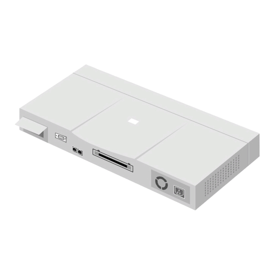
10BASE-T Stackable Hubs XTERNAL EATURES NDICATORS This chapter introduces the controls and connectors on the front and rear panels of the hub, and explains the front panel display in detail. Figures 2-1, 2-2 and 2-3 show the layouts of the front panel, rear panel, and display of the stackable hubs. -
Page 16: E Xternal F Eatures And I Ndicators
10BASE-T Stackable Hubs AUI Connector Daisy-chain Port The following components are found on the front and back panels of the hubs: ♦ Ethernet Ports Used for connecting the hub to network devices using 10BASE-T shielded or unshielded twisted-pair cable. The X label marked on each port means the ports are MDI-X ports, which connect to workstations and servers using straight-through cables and to other hubs using crossover cables. -
Page 17: Front Panel Indicators
♦ AUI Port Used when connecting the hub to a 10BASE5 "thick Ethernet" backbone, or to other types of Ethernet media. The recessed AUI port accommodates most standard transceivers (also known as Media Access Units or MAUs), allowing the transceiver to be safely and conveniently tucked away. - Page 18 10BASE-T Stackable Hubs The hub's front panel display features the following indicators: ♦ Port Status Indicators Each of the ports has an LED status indicator for reporting its link and activity status, and showing whether or not it has been partitioned. The port status indicators always come on when the hub is powered on.
- Page 19 ◊ Manual Partition The indicator of a port lights amber continually when the port is manually partitioned. Manually partitioning a port has the same effect as automatic partitioning, except that you must also manually re-enable it. You can choose to manually partition a port even if there is nothing wrong with it, for example to prevent a certain device from accessing the network or to reduce network traffic.
- Page 20 10BASE-T Stackable Hubs ♦ Late Col (manageable models only) The Late Col indicator lights when a collision is detected that happened after the 512th bit of a frame. Late collisions may be caused by overly long delays in the Ethernet network, either due to cable that is too long or a repeater (hub) count that is too high.
- Page 21 10BASE-T Stackable Hubs connected together into a single Ethernet “collision domain” through the daisy chain connectors on the back. Segmenting a hub places it in its own collision domain, while allowing it to be managed with the rest of the stack. External Features and Indicators...
- Page 22 10BASE-T Stackable Hubs ♦ Daisy-chain in/out The down arrow indicates that another hub in the stack is connected to the daisy-chain in port of the hub, and the up arrow indicates that another hub is connected to the daisy-chain out port. ♦...
-
Page 23: Setting U P The Hub
10BASE-T Stackable Hubs ETTING P THE This chapter explains how to choose a place for your hub stack and how to set up your hubs. Power and Environmental Requirements The hubs feature an auto-selecting 100-240 V, 50-60 Hz power supply unit, which works in most countries around the world. -
Page 24: Power Connection
10BASE-T Stackable Hubs ♦ Tandem blade ♦ Grounding type attachment plug rated at 15 A, 250V When using a 230V power source outside of the U.S., use a cord with the following characteristics: ♦ 18 AWG ♦ Grounding attachment plug rated at 15A, 250V ♦... -
Page 25: Free-Standing Installation
10BASE-T Stackable Hubs Free-standing Installation If you are installing the hub as a free-standing unit, apply the four self- adhesive rubber feet to the bottom of the hub chassis. Make sure the bottom surface of the chassis is clean and dry. Stand the chassis up-on-end and attach one rubber foot about 1 inch from each corner. -
Page 26: Installing The Transceiver Tray
10BASE-T Stackable Hubs Installing the Transceiver Tray At the rear of the hub, there is an AUI connector designed for connecting the hub to various types of Ethernet media such as thick Ethernet coaxial cable (10BASE5), thin Ethernet coax (10BASE2), or fiber optic cabling (10BASE- FL). -
Page 27: Replacing The Power Supply
Replacing the Power Supply The hub comes with a removable power supply for easy replacement. In the unlikely event that the power supply fails or is damaged, follow the steps below to replace the power supply. Disconnect the power cord from the AC outlet. Disconnect the power cord from its connector on the rear of the hub. -
Page 29: Building Hub Stacks
You can combine up to eight hubs in the Intelligent Series into a single manageable hub stack. Building a hub stack has two advantages: ♦ All of the hubs can be managed as a single unit using a network management system or the console interface. Up to 192 10BASE-T ports can be controlled and monitored from a single management screen. -
Page 30: Position Within The Stack
10BASE-T Stackable Hubs can take on different roles depending on the type of hub it is and its position in the hub stack. Position Within the Stack Hubs in the hub stack are connected using the daisy-chain ports located at the rear of the hub. -
Page 31: Slave Hub Roles
10BASE-T Stackable Hubs another master hub upstream. If it receives commands from a master hub, it becomes a Standby Master, controlled by the Active Master. If it does not receive any commands, or if the Active Master hub fails, it will become the Active Master. -
Page 32: Hub Id
10BASE-T Stackable Hubs When there is a working Active Master in the stack, then each slave hub in the stack will be a Managed hub controlled by the Active Master hub, and will have its own Hub ID. Hub ID Hub ID numbers, displayed on the front of the hub, are determined automatically by the master hub. -
Page 33: Segmenting Hubs
10BASE-T Stackable Hubs Figure 4 -2 Daisy-Chaining Hubs Segmenting Hubs The emergence of Ethernet switching hub technology has made it more common to segment local area networks into smaller pieces to reduce congestion on each segment. This makes it easier to balance network loads, since a smaller number of devices compete for the 10Mbps bandwidth on each network segment. - Page 34 10BASE-T Stackable Hubs Figure 4 -3 All Hubs Connected to Ethernet Backbone Figure 4 -3 shows an unsegmented stack of hubs. All hubs in the stack are in the same collision domain because they are connected together using the daisy-chain ports and they have not been segmented. Figure 4 -4 shows a stack divided into three separate collision domains.
- Page 35 Figure 4 -4 Three Separate Collision Domains When a hub is segmented from the rest of the stack, the Segmented indicator on the front panel display will light. For information about segmenting hubs using the console interface, see Chapter 6 in this User's Guide. information about segmenting hubs using the network management module for the hub, see the management module's User's Guide.
-
Page 37: Network Connections
10BASE-T Stackable Hubs ETWORK ONNECTIONS Once you have set up your hubs and connected them into a stack, you are ready to connect network stations, and to connect your hub to the rest of your Ethernet network. This chapter tells how to connect workstations to the hub, and the hub to the other hubs and network components on your local area network. - Page 38 10BASE-T Stackable Hubs Plug the RJ-45 connector at one end into the network station, and the other end into a free 10BASE-T port on the front of the hub. When both the hub and the device at the other end of the connection are turned on, and the cable is connected at both ends, then the Link indication for the port should light.
-
Page 39: Cascading Hub Stacks
10BASE-T Stackable Hubs Cascading Hub Stacks If you need to expand your network beyond an eight-port stack, or you need to connect your hub to other parts of your network, you can cascade it using several different network media, including 10BASE-T twisted-pair cabling, 10BASE2 thin coaxial cabling, 10BASE5 thick coaxial cabling, and FOIRL or 10BASE-FL fiber optic cabling. - Page 40 10BASE-T Stackable Hubs This means you can cascade to another hub using an ordinary straight- through twisted-pair cable. Figure 5 -2 Uplink Switch Setting When using this method, set the Port 1 Uplink switch to MDI, connect one end of the straight-through cable Port 1 of the hub, and connect the other end of the cable to an ordinary (non-uplink) port on the other repeater hub or Ethernet switch.
-
Page 41: Using Thin Coaxial Cabling
10BASE-T Stackable Hubs Using Thin Coaxial Cabling With the addition of a 10BASE2 transceiver connected to the AUI port at the rear of the hub (as described in Chapter 3), you can cascade the hub to other hubs or stations using thin coaxial cabling. This method of cascading hubs gives additional flexibility over using twisted-pair cable, since you can cascade up to thirty hubs on a single thin coaxial cable segment. -
Page 42: Multilevel Cascading
10BASE-T Stackable Hubs When connecting a transceiver to the hub, the transceiver's SQE (heartbeat) function should be disabled. Multilevel Cascading Hubs can be cascaded in multiple levels, provided no path between stations on the network goes through more than four repeaters. For example, a backbone level of hubs can be connected in a bus using 10BASE2 cabling, and second-level workgroup hubs can be connected to the backbone hubs using twisted-pair cabling. -
Page 43: Using The Console Interface
10BASE-T Stackable Hubs SING THE ONSOLE NTERFACE Your Intelligent stackable Ethernet hub supports a console management interface that allows you to set up and control your hub, either with an ordinary terminal (or terminal emulator), or over the network using the TCP/IP Telnet protocol. -
Page 44: Console Usage Conventions
10BASE-T Stackable Hubs ♦ 8 data bits ♦ No parity ♦ One stop bit You can also access the same functions over a Telnet interface. Once you have set an IP address for your hub, you can use a Telnet program (in a VT- 100 compatible terminal mode) to access and control the hub. -
Page 45: Logging In To The Hub Console
Logging In to the Hub Console The Intelligent Series master hubs support user-based security that can allow you to prevent unauthorized users from accessing the hub or changing its settings. This means that before you can access the functions of the hub, you will need to first log into the hub, giving a password. - Page 46 10BASE-T Stackable Hubs With the cursor on the OK selection, press Enter. The main menu screen will be displayed. NOTE: When the hub is shipped from the factory, the default user name is SNMP-T and the default password is also SNMP-T. You will need to use this user name and password when you first set up your hub or if you have completely reset the hub settings using the...
-
Page 47: Changing Your Password
Changing your Password To change your user password: Choose User Account Change from the main menu. Choose Change Password Figure 6 -3 Change Password Type in your user name and press Enter. Type in your old password and press Enter. Type in the new password you have chosen, and press Enter. -
Page 48: Setting Up The Master Hub
10BASE-T Stackable Hubs This method can also be used by a Super User to change another user’s password. Setting up the Master Hub This section describes the settings you will need to change to allow you to be able to manage the hub from an SNMP-based Network Management System such as SNMP-View, or to be able to access the hub using the Telnet protocol. - Page 49 ♦ Default Gateway: IP address that determines where frames with a destination outside the current subnet should be sent. This is usually the address of a router or a host acting as an IP gateway. If your network is not part of an internetwork, or you do not want the hub to be accessible outside your local network, you can leave this field blank.
-
Page 50: Out-Of-Band Management And Console Settings
10BASE-T Stackable Hubs Out-of-band management and console settings You can use the Out-of-Band/Console Setting menu to choose whether to use the hub’s RS-232C serial port for console management or for out-of-band TCP/IP communications using SLIP, and to set the bit rate used for SLIP communications. -
Page 51: Software Updates
Figure 6 -5 Out-of-Band/Console Setting Menu Software Updates The hub is capable of obtaining its boot-time configuration information, as well as updated versions of its internal firmware, using TFTP (the Trivial File Transfer Protocol) and BOOTP (the BOOTstrap Protocol). You can use the Software Update menu to control this feature. - Page 52 10BASE-T Stackable Hubs ♦ Boot Server IP Address The IP address of the TFTP server where the configuration file is located. This entry is used only if the S/W Update Control is enabled and your boot protocol is you are using bootp-tftp Power Up is enabled, the address will be obtained from the BOOTP server.
-
Page 53: Snmp Information
SNMP Information The System Configuration Menu screen shows various pieces of information about your hub, and allows you to set the System Name, System Location, and System Contact. These settings can be retrieved from the hub using SNMP requests, allowing these settings to be used for network management purposes. -
Page 54: Snmp Traps
10BASE-T Stackable Hubs The System Configuration Menu also contains the Console/Telnet Display Timeout parameter, which determines how long the console may sit idle before the user is “logged out.” SNMP Traps The hub sends out SNMP traps to network management stations whenever certain exceptional events occur, such as when the hub is powered on or when an SNMP request is made using an unknown community name. -
Page 55: Snmp Security (Community Names)
10BASE-T Stackable Hubs ♦ Status: determines whether this trap entry is valid or invalid. You can delete an entry by changing its status to Invalid. SNMP Security (Community Names) SNMP (version 1) implements a rudimentary form of security by requiring that each request include a community name. -
Page 56: Adding And Deleting Users
10BASE-T Stackable Hubs Adding and Deleting Users Access to the console, whether using the console port or via Telnet, is controlled using a user name and password. Up to three of these user names can be defined. One user, named SNMP, is defined by default; this user name can be removed if desired. - Page 57 Choose SAVE and press Enter to let the user addition take effect. Choose EXIT to leave the Create New User menu. To delete a user, Choose User Account Change from the main menu. Choose Delete Users from the User Account Change menu. Toggle the Delete field of the user you wish to remove to Yes.
-
Page 58: Hub Stack Configuration
10BASE-T Stackable Hubs Choose SAVE and press Enter to let the user addition take effect. Choose EXIT to leave the Delete Users menu. Hub Stack Configuration Several important hub parameters useful in the day-to-day management of the hub can be viewed and controlled using the Group Configuration, Primary/Backup Master Menu, and Port State menus. -
Page 59: Controlling Hubs In The Hub Stack
Figure 6 -13 Primary/Backup Master Menu Controlling Hubs in the Hub Stack The Group Configuration Menu screen, found within the Network Monitoring menu, displays information about each of the hubs in the stack, and allows you to make the Hub ID indicator flash. The items displayed on this screen are: ♦... - Page 60 10BASE-T Stackable Hubs ♦ Group Port Capacity: shows the total number of controllable ports (includes the UTP ports, AUI ports, an internal management port, etc.) ♦ Group Hardware Revision: shows the design version of the hub hardware. ♦ Group Status: shows whether the hub is up or down. ♦...
-
Page 61: Controlling Individual Ports
You can use the PREV GROUP and NEXT GROUP commands to switch to another hub, or you can enter the hub’s Group ID number directly into the Group ID field. Controlling Individual Ports The Port State Menu, accessible from the Network Monitoring menu, allows you to view the status of individual ports and to control their settings. -
Page 62: Segmenting Hubs
10BASE-T Stackable Hubs ♦ Auto Partition: displays On if the port has been automatically partitioned off from the rest of the network due to excessive errors, and Off if the port is operating normally. ♦ Admin State: this toggle determines whether the port should be enabled or disabled (manually partitioned). -
Page 63: Monitoring The Hub Stack
To segment an individual hub from the rest of the stack: Enter the Port State Menu Screen, accessible from the Network Monitoring Menu. Select the Group ID of the hub you wish to segment. Select Port 25 for the 24-port hub models, or Port 13 for the 12-port hub models. - Page 64 10BASE-T Stackable Hubs choose which to view through the Statistics menu, accessible from the Network Monitoring menu. Figure 6 -16 Network Monitoring Menu The statistics shown are the same for each of these selections. The statistics displayed are: ♦ Too Long Frame: counts frames longer than the 1518-byte (octet) limit set by the Ethernet standard.
- Page 65 are too long, and you have either exceeded the repeater count or cable length specified in the Ethernet standard. ♦ Runt Frame: counts frames shorter than the 64-byte (octet) minimum defined by the Ethernet standard. collisions. ♦ Collision: counts collisions on the Ethernet segment. ♦...
- Page 66 10BASE-T Stackable Hubs ♦ Broadcast Frame: counts valid frames that are broadcast to all stations on the network. ♦ 64 Octs, 65-127 Octs, 128-255 Octs, 256-511 Octs, 512-1023 Octs, 1024-1518 Octs: Counts frames of various length ranges, both valid and invalid. ♦...
-
Page 67: Displaying Node Tracking Information
10BASE-T Stackable Hubs Displaying Node Tracking Information The Node Tracking Information screen, accessible from the Network Monitoring menu, displays the source and destination addresses of packets recently received on a given port. Ethernet (MAC) addresses are displayed for all packets, and IP addresses are displayed for packets conforming to the IP protocol. -
Page 68: Factory Reset
10BASE-T Stackable Hubs Resetting the Hub You can use the console interface to reset the hub stack, either doing a System Reset (which restarts the hub and is identical to powering the hub off and back on again) or a Factory Reset (which sets all of the hub’s parameters to what they were when the hub was delivered from the factory). -
Page 69: Factory Reset
Factory Reset Before performing a factory reset, be absolutely certain that this is what you want to do. Once the reset is done, all of the hub’s settings stored in NVRAM (including enabled/disabled settings of ports, security settings, etc.) will be erased and restored to their factory default settings. -
Page 71: A S Pecifications
Interface IEEE 802.3 10BASE-T Twisted-pair ports IEEE 802.3 10BASE5 AUI Port RS-232 port Daisy chain port Display Indicators For each TP Port: Link For each TP, AUI Port: Data reception Auto Partition Manual Partition Daisy-chain Link Collision Utilization % Hub Unit ID Standby/Master Console/Out-of-band Feature... - Page 72 10BASE-T Stackable Hubs Weight Dimensions Operating Temperature Network Management RFC-1157 (SNMP), RFC- 1155 (SMI), RFC-1213 (MIB-II), RFC-1368 (Repeater MIB), SNMP Proprietary MIB In-band Management Out-of-band Management Management CPU Boot EPROM Flash Memory for Firmware Management RAM Memory Master or Passive in Cascading 240VAC, 240VAC,...
-
Page 73: B Power -O N Self Test
OWER When the master hub is powered on, it does a Power-On Self Test (POST) to verify that all of its components are working properly. As it performs its tests, the test progress is displayed on the terminal console, provided the hub is in console mode. - Page 74 10BASE-T Stackable Hubs will halt, the Hub ID “A” indicator will flash, and the last frame lit in the series will show what test failed. The parts of the Power-on Self Test, and the indicator associated with each part, are as follows: PROM Test (Port 1 Frame) Tests the integrity of the hub’s internal Read-Only Memory.
- Page 75 When the power-on self-test is completed, the hub begins its boot sequence. If you are using out-of-band software downloading, the hub waits for 5 seconds to give you an opportunity to stop the boot process by pressing Control-C (and blinks the Port 3 and Port 4 frames), before beginning the download.
- Page 76 10BASE-T Stackable Hubs Duplicate IP address detected ◊ F Invalid IP address or subnet mask TFTP Download (Port 3 Frame/Port 9 Frame) The hub uses the TFTP protocol to load its boot configuration file, and optionally the run-time image. This step is omitted if the hub is configured to not use TFTP.
- Page 77 ordinary memory in preparation for use. This is the last step in the boot process. Error codes in this step include: ◊ 1 Local Flash Download Error (Flash Memory Checksum Error) ◊ 2 Local Flash Download Error (Run Time Image Error) Power-On Self Test 10BASE-T Stackable Hubs...
-
Page 79: C Boot Configuration File
The master hubs in the series support a powerful configuration file which allows many of the hub stack’s configuration parameters to be stored on a centralized server. When the master hub starts up, it can be configured to read its configuration file from the server using the TFTP protocol. This can make it easier to manage a large number of hub stacks, since all of the configuration parameters for all of the hubs can be managed in a single place. - Page 80 10BASE-T Stackable Hubs contact information for the person responsible for administering the hub. The string can be up to 64 characters long. ♦ syslocation Takes string as the System Location, corresponding to the SNMP MIB II variable sysLocation. location of the hub for administrative purposes. The string can be up to 64 characters long.
- Page 81 Enables or disables authentication failure traps for invalid SNMP community names. The argument may be ♦ clear-SNMP-comm-table Clears the hub’s SNMP community name table. ♦ SNMP-community Adds community to the hub’s list of SNMP communities, with access permissions. The community name can be up to 32 characters long. Permissions can be read for read-write community access.
-
Page 83: Dc Ables And Connectors
Ports 2 through 24 are MDI-X 10BASE-T Ethernet ports. Port 1 is a 10BASE-T Ethernet port, with a sliding switch that enables a connection to a network station (in the MDI-X setting) or to a repeater, bridge, or hub (in the MDI setting). -
Page 84: Crossover Cable
10BASE-T Stackable Hubs Workstation (MDI) Figure D-2 Straight-through Cable Crossover Cable When cascading or connecting the hub to another switch, bridge, or hub through the UTP port, a modified crossover cable is necessary. With a crossover cable, two pairs of wires are switched at one connector end. Carry out the following steps to create a customized, crossover twisted-pair cable: Leave one end of the cable as is, with the RJ-45 connector intact. -
Page 85: Daisy-Chain Cable
Daisy-chain Cable The hubs use ordinary Category 5 twisted-pair cable with RJ-45 connectors on each end for stacking. All four pairs of the eight-wire cable are used. A 30cm daisy-chain cable is included with the hub; this information is included in case you want to make your own, longer cable. - Page 86 10BASE-T Stackable Hubs Console Port (DCE, DB-9) DCD (1) RXD (2) TxD (3) DTR (4) DSR (6) RTS (7) CTS (8) Figure D-4 Local Connection to 9-Pin Serial Port Console Port (DCE, DB-9) DCD (1) RXD (2) TxD (3) DTR (4) DSR (6) RTS (7) CTS (8)
- Page 87 Console Port (DCE, DB-9) DCD (1) RXD (2) TxD (3) DTR (4) SG (5) DSR (6) RTS (7) CTS (8) Figure D-7 Remote (Modem) Connection to 25-Pin Serial Port Cables and Connectors 10BASE-T Stackable Hubs Modem (DCE, DB-25) DCD (8) RXD (3) TxD (2) DTR (20)
Need help?
Do you have a question about the DE-1824EI and is the answer not in the manual?
Questions and answers