
Related Manuals for Zodiac Z700 DUO Series


Summary of Contents for Zodiac Z700 DUO Series
- Page 1 Z700 DUO Instructions for installation and use - English Heat pump Translation of the original instructions in french More documents on: www.zodiac.com H0590900_REVA - 2018/04...
- Page 2 • Zodiac® heat pump, filtration pump and filter appliances are compatible with the most commonly used types of pool water treatment systems. • Do not touch the fan or moving parts and do not place any objects or your fingers in the vicinity of the moving parts during operation of the appliance.
-
Page 3: Table Of Contents
The distribution or modification of this document in any way is prohibited, without prior • authorisation from Zodiac®. Zodiac® continuously develops its products to improve quality. The information contained in • this document may therefore be modified without notice. CONTENTS ❶... -
Page 4: ❶ Installation
❶ Installation 1.1 I Selecting the location • When installed with and protected by an appropriate Residual Current Device (RCD) having a maximum trip current rating of 30mA, the appliance must be installed at 2 metres, minimum, from the surrounding edge of the pool. •... -
Page 5: I Hydraulic Connections
1.2 I Hydraulic connections 1.2.1 Pool water circuit • The connection is made with a Ø50 PVC pipe to the pool filtration circuit, after the filter and before the water treatment, using the unions supplied. • Ensure that the hydraulic connection fitting direction is correct. •... -
Page 6: I Power Connections
: Mains water inlet (filling valve) : Water outlet : Heat pump Z700 DUO : Zodiac® dehumidifier 1.3 I Power connections • Before carrying out any work inside the appliance, it is essential to disconnect the electrical supply as there is a risk of electric shock which can cause damage to equipment and property, serious injury and even death. - Page 7 • Compulsory connection. • Use cables with a section of at least 2 x 0.75 mm². • Connect heat pump terminals 8 and 9 to the Zodiac® dehumidifier terminals 3 and 6. : Z700 DUO heat pump terminal : Zodiac® dehumidifier terminal 1.3.3 Connecting the filtration pump (heating priority)
-
Page 8: I Connecting The Options
1.4 I Connecting the options • Any incorrect connection to the terminal can damage the appliance and void its warranty. • When working on the terminal, there is a risk of electrical return current, injury, damage to equipment and property and death. •... -
Page 9: ❷ Use
According to the temperature set by the user, the heat pump either heats the pool water, or heats a water circuit designed to power the heating coil of a Zodiac® dehumidifier in order to heat the air. In the theoretical event of a request for both at the same time, priority is given to heating the air. -
Page 10: I User Interface Overview
2.2 I User interface overview • Brief press: return to menu tree or exit a setting. • Brief press from the home screen (see diagram below) to display the alarms manager (see “4.2 I Alarm display”). • Press and hold (3 seconds): to switch the appliance on or off when it is connected to the power supply. -
Page 11: I Operation
2.3 I Operation 2.3.1 Switching on the pool circuit • Check that there are no tools or other foreign objects in the machine. • Check that the access panel to the technical section is closed properly, • Set the valves to the following positions: valve fully open;... - Page 12 2.3.3 Switching on the heat pump • Check that the filtration pump timer is connected correctly; see “1.3.3 Connecting the filtration pump (heating priority)”. • Connect the power supply to the heat pump. The message is displayed for several seconds and the ON LED is lit. •...
- Page 13 2.3.5 Adjusting the heat pump timer (RTC) • From the home screen press and hold for 3 seconds. • A new menu is displayed. Go to “RTC” (timer) by pressing and then confirm by pressing : the date and time are displayed: •...
-
Page 14: ❸ Maintenance
❸ Maintenance 3.1 I Winterizing • Winterizing is essential if the heat pump is shut down during the winter period. In this case, it is necessary to prepare all the circuits for winter to avoid damaging the condenser and/or plate heat exchanger, its circulating pump and electric heater, due to frost. This is not covered by the warranty. -
Page 15: ❹ Troubleshooting
❹ Troubleshooting • If an operating fault occurs, please carry out these few simple checks using the tables below before contacting your retailer. • If the fault continues, contact your retailer. • : Actions are to be carried out by a qualified technician only 4.1 I Appliance performance •... -
Page 16: I Alarm Display
4.2 I Alarm display • An alarm is reported by flashing of the symbol on the main home screen. • Press to go to the “Alarms” menu. Two types of information are displayed: = alarm code = alarm meaning Press = see next alarm. - Page 17 §”2.3.5 Adjusting the heat pump timer RTC discharged/broken more than 72 hours = RTC discharged (RTC)”). • RTC broken • If this fails, contact the Zodiac® Technical Department AP01 • The component has reached the number Circulating pump operating hours of operating hours.
-
Page 18: I Additional Menus
4.3 I Additional menus • From the home screen, press to access the menus. • Press to scroll through the menus. Pool water temperature Pool water temperature setpoint (SP = Set Point) Dehumidifier heating water inlet temperature Dehumidifier heating water temperature setpoint Compressor status (ON = in operation / OFF = stopped) Evaporator temperature Defrost mode activation temperature... -
Page 19: I Wiring Diagram
4.4 I Wiring diagram 4.4.1 Wiring diagram for single-phase models CEM 1 230 V 12 V 24 V CMDD V ≈ - V ≈ + +12V A / - A / + WPS (shunt) CAN - CAN + C3Pro micro plus CO6/7 CO1/2 CO3/4... - Page 20 4.4.2 Wiring diagram for three-phase models 230 V L1 L2 L3 12 V 24 V CMDD V ≈ - V ≈ + +12V A / - A / + WPS (shunt) CAN - CAN + C3Pro micro plus CO3/4 CO6/7 CO1/2 25 26 20 21...
- Page 21 Symbol Description Phase sequence controller Compressor contactor Electric heater switch Condenser 80 µf 3.15 A fuse 5 x 20 Low pressure switch High pressure switch Dehumidifier water circuit pressure switch Cooling fan motor assembly 4-way valve Dehumidifier water circulating pump Pool water circuit solenoid valve Dehumidifier water circuit solenoid valve Flow switch...
-
Page 22: ❺ Features
❺ Features 5.1 I Description *Accessible via front panel of appliance Z700 DUO Pool circuit condenser plug (x 2) Dehumidifier circuit exchanger plug (x 2) Connection Ø50 and seal (x 2) Connection Ø28 and seal (x 2) Air heating hydraulic connection kit Anti-vibration studs (x 4) Remote control Condensate tray... -
Page 23: I Technical Specifications
5.2 I Technical specifications Z700 DUO -8 to 38 °C pool water from 10 to 32°C Operating temperature range dehumidifier from 10 to 50°C water 220-240 V - 50 380-415 V - 50 220-240 V - 50 380-415 V - 50 Voltage Admissible variation in voltage ±... -
Page 24: I Dimensions And Marking
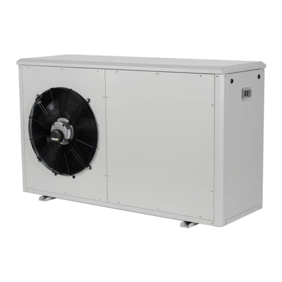
5.3 I Dimensions and marking : Base Front : Fan : Evaporator : Cable gland : Pool water inlet : Pool water outlet : Air heating water inlet : Air heating water outlet : Technical access door : User interface Overall dimensions Side... - Page 25 Your retailer Modèle appareil Appliance model Numéro de série Serial number Pour plus d’informations, enregistrement produit et support client : For more information, product registration and customer support: www.zodiac.com ZODIAC® is a registered trademark of Zodiac International, S.A.S.U., used under license.
Need help?
Do you have a question about the Z700 DUO Series and is the answer not in the manual?
Questions and answers