Zodiac Z200 Defrost Instructions For Installation And Use Manual
Hide thumbs
Also See for Z200 Defrost:
- Instructions for installation manual (12 pages) ,
- Instructions for installation and use manual (28 pages) ,
- Instruction manual and spare parts list (10 pages)

Related Manuals for Zodiac Z200 Defrost


Summary of Contents for Zodiac Z200 Defrost
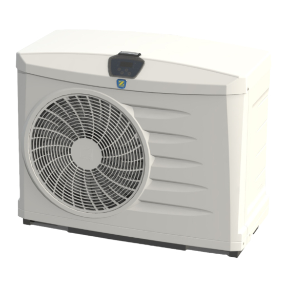
- Page 1 Z200 Defrost Z200 PI20 Defrost Instructions for installation and use - English PI20 Heat pump Translation of the original instructions in French More documents on: www.zodiac.com H0548500_REVF - 2021/02...
- Page 2 WARNINGS This symbol shows that This symbol shows that this information is available such appliance uses R32, a low burning as the Operating Manual or velocity refrigerant. Installation Manual. This symbol shows that a service This symbol shows that the personnel should be handling this Operation Manual should be read equipment with reference to the...
- Page 3 • Do not touch the fan or moving parts and do not place any objects or your fingers in the vicinity of the moving parts during operation of the appliance. Moving parts can cause serious injury or even death. WARNINGS ASSOCIATED WITH ELECTRICAL APPLIANCES •...
- Page 4 INSTALLATION AND MAINTENANCE • The appliance may not be installed close to combustible materials, or an air duct inlet of an adjacent building. • With some appliances, it is essential to fit protection grids if the unit is installed in an area with uncontrolled access.
-
Page 5: Table Of Contents
CONTENTS ❶ Specifications 1.1 I Description 1.2 I Technical specifications 1.3 I Dimensions and marking ❷ Installation 2.1 I Selecting the location 2.2 I Hydraulic connections 2.3 I Electricity supply connections 2.4 I Option connection ❸ Use 3.1 I Operating principle 3.2 User interface presentation 3.3 I Operating 3.4 I User functions... -
Page 6: ❶ Specifications
❶ Specifications 1.1 I Description *In the polystyrene cap above the heat pump Z200 PI20 Joint (x2) Screw-in connector (x2) Ø40 adaptation (x2) Ø50 reduction (x2) Condensation evacuation kit (Ø15) Winterizing cap (x2) Winterizing cover Heating priority Remote control PAC NET (cleaning product) Wall mounting kit : supplied... -
Page 7: I Technical Specifications
1.2 I Technical specifications Standards Defrost Z200 PI20 PI2021 PI2031 PI2041 PI2051 PI2021D PI2031D PI2041D PI2051D 5 to 32°C - 5 to 32°C Operating temperature range water up to 32°C Operating power* 10.1 Power supply 220-240 V / 50Hz Defrosting by forced air circulation Defrosting by cycle inversion Acceptable variation in voltage -10%, +7% (during operation) -
Page 8: I Dimensions And Marking
1.3 I Dimensions and marking : Protection valve and user interface : Ventilator : Technical access door : Pool water intake : Pool water output Front + side : Evaporator : Grommet for heating priority cable run* : Location for drilling for remote control cable run* *depending on the model Rear... -
Page 9: ❷ Installation
❷ Installation 2.1 I Selecting the location • The appliance must be installed at 2 metres, minimum, from the surrounding edge of the pool. • Do not lift the device by the body; use its base. • Install the device outdoors; provide free space around it (see § “2.2 I Hydraulic connections”). •... -
Page 10: I Hydraulic Connections
2.2 I Hydraulic connections • The device will be connected with a Ø40 or Ø50 PVC pipe, using the connectors supplied (see § “1.1 I Description”), to the pool's filtration circuit, after the filter and before the water treatment. • Respect the direction of hydraulic connection ( = input and = output). -
Page 11: I Electricity Supply Connections
2.3 I Electricity supply connections • Before any work inside the device, you must cut the electricity supply as there is a risk of electric shock which may cause material damage, serious injury or even death. Incorrectly tightened terminals may cause the terminal unit to heat up and invalidate the •... -
Page 12: I Option Connection
2.4 I Option connection 2.4.1 "Heating priority" option (depending on model) • This function allows the unit to start the filtration (in 5 minutes cycle every 220 minutes) to detect the water temperature and thus switch on the filtration + heating unit to maintain this temperature at a constant value. It is said that the filtration pump is slaved to the heating system. -
Page 13: ❸ Use
❸ Use 3.1 I Operating principle Your heat pump uses the calories (heat) in the air to heat up your pool's water. The process to heat your pool's water to the temperature you want may take a few days as it depends on the weather conditions, your heat pump's power and the difference between the water temperature and the temperature you want. -
Page 14: I Operating
3.3 I Operating • Check that there are no tools or other foreign objects in the machine. • The panel that provides access to the technical section must be put in place. • Set the valves as follows: valve B wide open, valves A, C, D and E closed : water entry valve : by-pass valve : water exit valve... -
Page 15: I User Functions
3.4 I User functions 3.4.1 Water temperature reading When the water is circulating through the heat pump, press flashes for 10 seconds then the setpoint temperature is displayed fixed. • To read the water temperature, it is imperative that the filtration is in operation and that the water flow indicator is fixed. -
Page 16: ❹ Maintenance
❹ Maintenance 4.1 I Winterizing • Winterizing is vital to prevent the condenser breaking due to freezing. This is not covered by the warranty. • To avoid damaging the equipment with condensation, do not fully cover it. • Switch off the device by pressing and holding for 2 seconds and disconnect it or switch off the electricity supply, •... - Page 17 approved by the manufacturer. When in doubt, contact the manufacturer’s technical department for assistance. • The following checks must be applied to installations using flammable refrigerants: - if an indirect cooling circuit is used, the presence of refrigerant in the secondary circuit must be analysed; - the markings on the equipment must remain visible and legible;...
- Page 18 • In addition to conventional charging procedures, the following requirements apply. - Check that there is no possibility of cross-contamination between the different refrigerants when using charging equipment. Hoses or lines must be as short as possible to reduce the quantity of refrigerant contained therein. - Cylinders must be kept in an appropriate position, in accordance with the instructions.
-
Page 19: ❺ Troubleshooting
❺ Troubleshooting • Before you contact your reseller, please carry out these few simple checks using the following tables if a problem occurs. • If the problem continues contact your reseller. • : Actions reserved for a qualified technician 5.1 I Device behaviour •... -
Page 20: I Error Code Display
5.2 I Error code display Display of Possible causes Solutions SD2 sensor is offline or incorrectly Sensor replacement connected Air temperature sensor fault SD3 sensor is offline or incorrectly Sensor replacement connected Deicing sensor fault Low pressure fault in the cooling circuit (if fault persists after Call an approved technician acknowledgement) -
Page 21: I Wiring Diagrams
5.3 I Wiring diagrams 5.3.1 "Standard" models L-N-PE 230V-1N-50Hz protected power supply Ventilator relay Digital display Auxiliary pump relay Earth Complementary relay Compressor condenser Compressor Ventilator condenser Ventilator Flow controller Water temperature sensor High pressure switch Air temperature sensor Low pressure switch Defrost sensor Fuse Transformer... - Page 22 5.3.2 "Defrost" models L-N-PE 230V-1N-50Hz protected power supply Ventilator relay Digital display Auxiliary pump relay Earth Complementary relay Compressor condenser Compressor Ventilator condenser Ventilator Flow controller Water temperature sensor High pressure switch Air temperature sensor Low pressure switch Defrost sensor Fuse Transformer Compressor relay...
- Page 23 Pour plus d’informations, enregistrement produit et support client : For more information, product registration and customer support: www.zodiac.com ©2021 Zodiac Pool Systems LLC. All rights reserved. ZODIAC® is a registered trademark of Zodiac International, S.A.S.U., used under license. All other trademarks are the property of their respective owners.
Need help?
Do you have a question about the Z200 Defrost and is the answer not in the manual?
Questions and answers