
Related Manuals for Zodiac iAquaLink Z400iQ


Summary of Contents for Zodiac iAquaLink Z400iQ
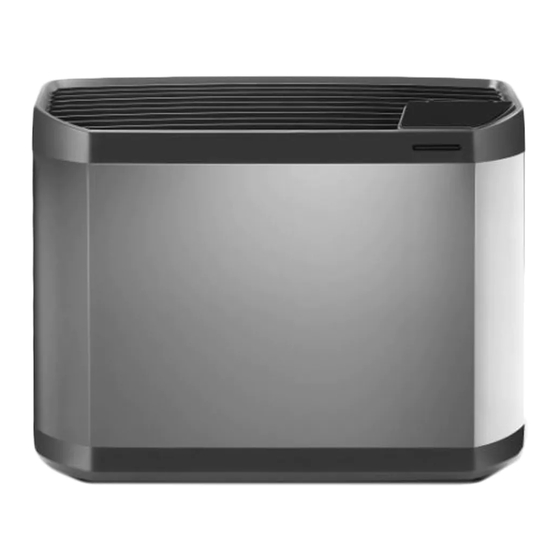
- Page 1 Z400iQ Instructions for installation and use - English Heat pump Translation of the original instructions in French More documents on: www.zodiac.com H0638700_REVI - 2021/06...
- Page 3 • The distribution or modification of this document in any way is prohibited, without prior authorisation from Zodiac®. • Zodiac® is constantly developing its products to improve their quality; therefore, the information contained in this document may be modified without notice.
- Page 4 WARNINGS ASSOCIATED WITH ELECTRICAL APPLIANCES • The electrical supply to the appliance must be protected by a 30 mA differential Residual Current protection Device (RCD), complying with the standards and regulations in force in the country in which it is installed. •...
- Page 5 • The appliance shall be stored in a room without continuously operating ignition sources (for example: open flames, an operating gas appliance or an operating electric heater). • Do not pierce or burn. • Be aware that refrigerants may not contain an odour. INSTALLATION AND MAINTENANCE •...
- Page 6 it is recommended good practice that all refrigerants are removed safely. • When transferring refrigerant into cylinders, ensure that only appropriate refrigerant recovery cylinders are employed. Ensure that the correct number of cylinders for holding the total system charge is available. All cylinders to be used are designated for the recovered refrigerant and labelled for that refrigerant (i.e.
-
Page 7: Table Of Contents
CONTENTS ❶ Installation 1.1 I Selecting the location 1.2 I Hydraulic connections 1.3 I Accessing the electrical connection terminal boards 1.4 I Power connections 1.5 I Connecting options ❷ Use 2.1 I Operating principle 2.2 I User interface presentation 2.3 I Operation 2.4 I User functions 2.5 I Connection to the iAquaLink™... -
Page 8: ❶ Installation
❶ Installation 1.1 I Selecting the location • The appliance must be installed at 2 metres, minimum, from the surrounding edge of the pool. • Do not lift the appliance by the body; use straps (not provided, see § “1.1.1 I Setting up the device“). - Page 9 Tip: reduce any noise annoyance from your heat pump • Do not install it under or towards a window. • Do not tilt it towards your neighbours. • Install it in an open space (sound waves are reflected on surfaces). •...
-
Page 10: I Hydraulic Connections
1.2 I Hydraulic connections • The device will be connected with a Ø50 PVC pipe, using the half union connectors supplied (see § ‘’5.1 I Description’’), to the pool's filtration circuit, after the filter and before the water treatment. • Respect the direction of hydraulic connection. •... -
Page 11: I Accessing The Electrical Connection Terminal Boards
1.3 I Accessing the electrical connection terminal boards Unscrew the 2 screws Slide the door downwards 1.4 I Power connections • Before any work inside the appliance, you must cut the electricity supply to the appliance as there is a risk of electric shock which may cause material damage, serious injury or even death. -
Page 12: I Connecting Options
1.5 I Connecting options Connecting the "Heating priority" and "On/off command" options: • Before any work inside the appliance, you must cut the electricity supply to the appliance as there is a risk of electric shock which may cause material damage, serious injury or even death. -
Page 13: ❷ Use
❷ Use 2.1 I Operating principle 2.1.1 General operation Your heat pump uses the calories (heat) in the air to heat up your pool's water. The process to heat your pool's water to the temperature you want may take a few days as it depends on the weather conditions, your heat pump's power and the difference between the water temperature and the temperature you want. -
Page 14: I Operation
2.2.2 Description of the display screen Symbol Name Steady Flashing Water flow too low or Water flow Water flow okay Appliance switched off missing Air temperature out of Air temperature in the Air temperature operating range operating range "Cold" mode “Cold”... -
Page 15: I User Functions
• The heat pump is on standby • Press for 2 seconds: (software version vary depending on the appliances) is displayed for 4 seconds, the last water temperature measured is then displayed This value varies depending on the last temperature recorded during the last connection. If no water flow was present during the last connection, the screen will display the value •... -
Page 16: I Connection To The Iaqualink™ App
2.4.4 Activating/deactivating “cold" mode Activation of «Cold» mode allows the machine’s cycle to be automatically reversed to cool the pool water when it exceeds the setpoint temperature by more than 2°C. • Press and hold • Press to display : •... -
Page 17: ❸ Maintenance
❸ Maintenance 3.1 I Winterizing • Although the device may be used year around, in the event that it will not be used during the winter months, proper winterizing is necessary in order to prevent damage to the condenser. Damage due to failure to properly winterize the unit when it is not use is not covered by the warranty. - Page 18 Area ventilation • Prior to penetrating the unit in any way to perform any required service, ensure that the area is open and adequately ventilated. Proper ventilation, to allow for safe dispersion of any refrigerant which may be inadvertently released to the atmosphere, should be maintained while service is being performed on the unit.
- Page 19 • Clean the outside of the appliance using a solvent-free product; a specific «PAC NET» cleaning kit is available as an accessory in the Zodiac catalogue for this purpose (see § ‘’5.1 I Description’’). 3.2.3 Maintenance to be carried out by a qualified technician •...
-
Page 20: ❹ Troubleshooting
❹ Troubleshooting • If a problem occurs, before you contact your retailer, please carry out these few simple checks using the following tables. • If the problem continues, contact your retailer. • : Actions to be performed by a qualified technician only 4.1 I Appliance behaviour •... -
Page 21: I Error Code Display
4.2 I Error code display Display of Possible causes Solutions Reset ST4 sensor temperature Wait until the exterior Automatic too low temperature rises Exchanger protection in "cooling" mode ST3 sensor temperature Clean the evaporator, if Automatic if ST3 sensor over 60°C or evaporator problem persists, call a qualified High temperature temperature below 45 °C... -
Page 22: I Lighting Of Leds On The Printed Circuit Board
By electricity supply Reconnect or change the Sensor is faulty or offline disconnection or automatic ST5 sensor fault - sensor if the fault disappears compressor discharge sensor Bad connection between Check the connectors on the the boards link cable between the boards •... -
Page 23: ❺ Characteristics
❺ Characteristics 5.1 I Description *In the appliance's box Z400iQ Winterizing cap (x2) Ø50 connector to be glued (x2) Winterizing cover Heating priority PAC NET (cleaning product) : supplied : available as an accessory... -
Page 24: I Technical Specifications
5.2 I Technical specifications Z400iQ MD4 MD5 MD7 -12 to 40 °C -12 to 38 °C -12 to 35 °C Operating temperatures water 15 to 32°C Defrosting by forced air circulation T°C air > 10°C Defrosting by cycle inversion T°C air < 10°C 380- 220- 380-... -
Page 25: I Dimensions And Marking
5.3 I Dimensions and marking Z400iQ 1030 1145 1027 *Overall dimensions in mm Front Side Rear : Base : Side panel : Technical access door : Front panel : Technical access : Pool water inlet Ø1’’ 1/2 : Grid door : Pool water outlet Ø... - Page 26 Schémas électriques / Wiring diagrams / Schaltplan / Elektrischschema / Esquema eléctrico / Esquema eléctrico / Schema elettrico 1. Z400iQ MD4 - MD5...
- Page 27 2. Z400iQ MD7...
- Page 28 3. Z400iQ MD8...
- Page 29 4. Z400iQ MD9...
- Page 30 5. Z400iQ TD7 - TD8 - TD9...
- Page 31 English Deutsch Nederlands Français Carte électronique de PCB main Elektronische Elektronische stuurkaart régulation Steuerplatine Carte électronique (écran) PCB display Elektronikkarte (Display) Elektronische kaart (scherm) Carte électronique LED Led display Elektronikkarte LED Elektronische kaart LED Condensateur ventilateur Fan motor capacitor Kondensator für Lüfter Condensorventilator Condensateur deuxième speed capacitor...
- Page 32 Español Português Italiano Ελληνικά Tarjeta electrónica de Placa eletrónica de Scheda elettronica di Ηλεκτρονική κάρτα regulación regulação regolazione ελέγχου Tarjeta electrónica Placa eletrónica (ecrã) Scheda elettronica Ηλεκτρονική κάρτα (pantalla) (display) (οθόνης) Tarjeta electrónica LED Placa eletrónica led Scheda elettronica Led Ηλεκτρονική...
- Page 33 For more information, product registration and customer support: Europe: www.zodiac.com Australia: www.zodiac.com.au See warranty details on : ©2021 Zodiac Pool Systems LLC. All rights reserved. ZODIAC® is a registered trademark of Zodiac International, S.A.S.U., used under license. All other trademarks are the property of their respective owners.
Need help?
Do you have a question about the iAquaLink Z400iQ and is the answer not in the manual?
Questions and answers