
Subscribe to Our Youtube Channel
Related Manuals for Zodiac Z950


Summary of Contents for Zodiac Z950
- Page 1 Z950 Instructions for installation and use - English Heat pump Translation of the original instructions in french More documents on: www.zodiac.com 05470135_REV02...
- Page 3 WARNINGS Carefully read the instructions in this manual before using the unit. GENERAL WARNINGS • Failure to respect the warnings may cause serious damage to the pool equipment or cause serious injury, even death. • Only a person qualified in the technical fields concerned (electricity, hydraulics or refrigeration) is authorised to carry out maintenance or repair work on the appliance.
- Page 4 WARNINGS ASSOCIATED WITH ELECTRICAL APPLIANCES • The power supply to the appliance must be protected by a dedicated 30 mA Residual Current Device (RCD), complying with the standards and regulations in force in the country in which it is installed. •...
- Page 5 INSTALLATION AND MAINTENANCE • The appliance may not be installed close to combustible materials, or the air duct inlet of an adjacent building. • With some appliances, it is essential to fit a "protection grid"-type accessory if the unit is installed in an area with uncontrolled access. •...
- Page 6 RECOVERY • When draining the refrigerant for maintenance or decommissioning, best practices should be followed in order to safely drain all of the refrigerant. • When transferring refrigerant to a cylinder, make sure that you use a recovery cylinder that is compatible with the refrigerant. Make sure that the correct number of cylinders are provided for recovering all of the refrigerant.
-
Page 7: Table Of Contents
The distribution or modification of this document in any way is prohibited, without prior • authorisation from Zodiac®. Zodiac® is constantly developing its products to improve their quality. The information • contained herein may therefore be modified without notice. CONTENTS ❶... -
Page 8: Specifications
❶ Specifications 1.1 I Description Z950 TD35 TD45 TD60 TD90 TD120 Single cooling circuit Double cooling circuit Ø63 connector (x2) Ø75 connector (x2) Winterising caps (x2) PAC NET (cleaning product) : supplied : available as accessories... -
Page 9: I Technical Specifications
1.2 I Technical specifications Z950 TD35 TD45 TD60 TD90 TD120 -12 to 38 °C Operating temperatures water 10 to 40 °C Defrosting by cycle inversion Air T°C < 10 °C Voltage 400V/3/50 Hz Admissible variation in voltage ± 10 % (during operation) -
Page 10: I Dimensions And Marking
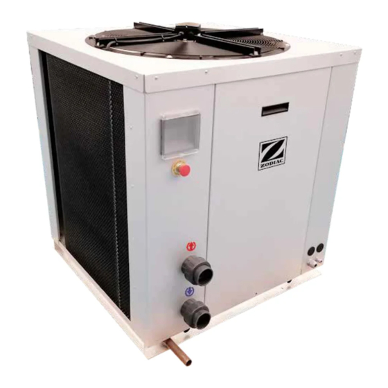
TD35 - TD45 TD60 -TD90 - TD120 Base Axial fan Interface utilisateur Evaporator Water Inlet/ Outlet Aluminium body Front and side Lifting points Bottom Z950 TD35 TD45 TD60 TD90 TD120 (mm) 1,050 1,050 1,300 1,300 1,300 (mm) 1,000 1,000 1,700... -
Page 11: ❷ Installation
❷ Installation 2.1 I Selecting the location • Installation is only permitted outdoors. • Do not lift the appliance by the body; use the dedicated points on its base (see § “1.3 I Dimensions and marking“). • When the appliance is installed and protected by a residual current device (RCD) with a maximum current of 30 mA, it should be installed at a distance of at least 2 metres from the edge of the pool. -
Page 12: I Hydraulic Connections
2.2 I Hydraulic connections • A by-pass must be installed to make it easier to work on the appliance. • The device will be connected to the pool's filtration circuit with a Ø63 or Ø75 PVC pipe (depending on the model) using the supplied connectors, after the filter and before the water treatment. -
Page 13: I Electrical Connections
2.3 I Electrical connections 2.3.1 Electrical power supply connection • Before any work inside the appliance, you must cut the appliance’s electricity supply as there is a risk of electric shock which may cause material damage, serious injury or even death. •... - Page 14 2.3.2 "Heating priority" option • Before any work inside the appliance, you must cut the appliance’s electricity supply as there is a risk of electric shock which may cause material damage, serious injury or even death. • Use cables with a section of at least 2x0.75 mm², RO2V type and with a diameter between 8 and 13 mm.
-
Page 15: ❸ Use
❸ Use 3.1 I Operating principle 3.1.1 General operation Your heat pump uses the calories (heat) in the air to heat up your pool's water. The process to heat your pool's water to the temperature you want may take a few days as it depends on the weather conditions, the heat pump's power and the difference between the water temperature and the temperature you want. - Page 16 Water temperature at outlet Operating mode Appliance status Error codes Operating condition of components 3.2.2 Description of the display screen Symbol Description Operating modes Heating mode activated Cooling mode activated Heating/Cooling mode activated Appliance status Turned off In standby Time programming activated Operating Defrosting Appliance stopped (frost protection)
- Page 17 Communication problem (RS485) Additional information Time setting Set point Alarm in progress Keypad locked 3.2.3 Presentation of the function keys "On/off" button Time setting button Temperature and consumption values display Operating mode setting button Go back in the menus Setpoint temperature adjustment button Electrical resistor activation button Value setting buttons...
-
Page 18: I Operation
3.3 I Operation 3.3.1 Starting up the appliance • Check that there are no tools or other foreign objects in the appliance, • Refit the panel providing access to the technical part (see § “1.3 I Dimensions and marking”), • Set the valves as follows: valve B wide open, valves A, C, D and E closed. : water inlet valve : by-pass valve : water outlet valve... -
Page 19: I User Functions
3.4 I User functions 3.4.1 Locking/unlocking the keyboard To lock or unlock the keyboard, press simultaneously for 5 seconds: the lock icon appears on the home screen when the keypad is locked and disappears when it is unlocked. 3.4.2 Time setting •... - Page 20 3.4.5 Sensor temperature reading • Press to display the temperature sensor values and the compressor consumption (the three values correspond to each of the compressor phases). • Press to display the different values (which are detailed in the table below) . Water inlet temperature Evaporator 1 sensor (defrost sensor) Discharge sensor 1...
- Page 21 3.4.6 Setting parameters (user accessible) The user can access the following parameters. Code Setting Values Factory settings Setpoint (in °C) 10 to 40 0: activated Heating Priority 1: deactivated 0: alarm silent Duration of audible alarm (in seconds) 0.1 - 10.0 (s) 606: until a key is pressed Calibration of the water inlet temperature -20 to 20...
-
Page 22: ❹ Maintenance
❹ Maintenance 4.1 I Winterising • Winterising is recommended if the appliance is not used for a long period. • In the case of winterising for the heat pump only, the appliance can be kept frost-free thanks to the condenser and compressor resistors. In this case, it can continue to be powered and the condensers will not require draining. -
Page 23: I Maintenance
• Clean the outside of the appliance using a solvent-free product; a specific "PAC NET" cleaning kit is available as an accessory in the Zodiac® catalogue for this purpose (see § “1.1 I Description”). 4.2.2 Maintenance to be carried out by a qualified technician •... -
Page 24: ❺ Troubleshooting
Troubleshooting ❺ • Before you contact your retailer, please carry out these few simple checks using the following tables if a problem occurs. • If the problem persists, contact your retailer. • : Actions to be performed by a qualified technician only 5.1 I Appliance behaviour •... -
Page 25: I Error Code Display
5.2 I Error code display Display Fault Possible causes Solutions No signal from the low-pressure Defective pressure switch, replace if switch necessary Low-pressure fault Leak in the cooling circuit Call a qualified technician. - circuit 1 Blocked evaporator, air flow too Remove any dirt or obstacles from the evaporator blocking the air flow Check that the 4-way valve is... - Page 26 Check the sensor reading and the Excessive compressor discharge Discharge cooling circuit temperature or system blockage temperature 1 or lack of gas fault Reconnect or change the sensor Check the sensor reading and the Excessive compressor discharge Discharge cooling circuit temperature or system blockage temperature 2 or lack of gas...
-
Page 27: I Advanced Setting Parameters (Accessible By A Qualified Technician)
5.3 I Advanced setting parameters (accessible by a qualified technician) Qualified technicians have a password allowing them access to all the settings listed in the following table. The settings which are accessible without a password are listed in § “5.3 I Advanced setting parameters (accessible by a qualified technician)”. - Page 28 Start defrosting temperature (in °C) -10 - 0 Stop defrosting temperature (en °C) 5 - 35 Start defrosting duration (min) 1 -120 Maximum defrosting duration (min) 3 - 20 Default temperature start defrosting (in -10 - 20 °C) Alarm delay time after defrosting 0 - 120 0: OFF 4-way valve mode...
- Page 29 Minimum ambient temperature for switching on the electrical resistance (in -10 - 20 °C) Maximum temperature difference between water inlet and outlet 0 - 20 temperature (in °C) Calibration of the defrosting temperature -20 - 20 sensor 1 (in °C) Calibration of the defrosting temperature -20 - 20 sensor 2 (in °C)
-
Page 30: I Advanced Operating Principles
• If F24 = 1 (only one compressor), the system 2 inputs and outputs are not used and no value is displayed. 5.4 I Advanced operating principles 5.4.1 Operating principles of modes The appliance has 4 operating modes: Heating, Cooling, Heating/Cooling. The user interface can be used to switch between these modes (see §... - Page 31 5.4.1.3 Heating/Cooling mode In Heating/Cooling mode, the appliance cools the water when the sensor temperature is higher than the setpoint temperature increased by the temperature differential of the Heating/Cooling mode (parameter F15). The appliance stops cooling the water when the temperature is below the setpoint temperature. The appliance heats the water when the sensor temperature is lower than the setpoint temperature reduced by the temperature differential of the Heating/Cooling mode (parameter F15).
-
Page 32: I Wiring Diagrams
5.4.3 I Operating principles of electrical protection 5.4.3.1 Protection system The compressor's time delay is configurable (see § “5.3 I Advanced setting parameters (accessible by a qualified technician)”, setting F21). This delay is used by the regulator to avoid continuous ON/OFF cycles. When the compressor stops following an operating phase, the regulator checks that this time has elapsed before it restarts the compressor. - Page 33 5.5 Schémas électriques / Wiring diagrams / Schaltplan / Elektrischschema / Esquema eléctrico / Esquema eléctrico / Schema elettrico 35 kW - 45 kW - 60 kW Schéma de commande / Control diagram / Steuerwirkbild / Bedieningsschema / Esquema de mando / Esquema de comando / Schema di comando...
- Page 34 Français English Deutsch Nederland Español Português Italiano TRIPPING Circuit de Uitschakel- Circuito de Circuito de Circuito di Auslösekreis CIRCUIT déclenchement circuit activación lançamento innesco FILTRATION Pompe de Bomba de Bomba de Pompa di Filterpumpe Filterpomp PUMP filtration filtración filtração filtrazione HIGH PRESSURE Pressostat Hogedruk-...
- Page 35 Schéma de puissance / Power supply diagram / Leistungswirkbild / Spanningschema / Esquema de potencia / Esquema de potência / Schema di potenza Français Deutsch Nederland Español Português Italiano EMERGENCY Parada de Paragem de Arresto Arrêt d’urgence Notstopp Noodstop STOP emergencia emergência d’emergenza...
- Page 36 CRANKCASE Résistance de Kurbelgehäuse- Carter- Resistencia de Resistência de Resistenza di HEATER carter Heizwiderstand weerstand cárter cárter carter Carte Elektronische Tarjeta Placa Scheda Elektronikkarte électronique kaart electrónica eletrónica elettronica THERMAL Relai Thermisch Thermorelais Relé térmico Relé térmico Relè termico RELAY thermique relais Ventilateur...
- Page 37 Français English Deutsch Nederland Español Português Italiano TRIPPING Circuit de Circuito de Circuito de Auslösekreis Uitschakel- circuit Circuito di innesco CIRCUIT déclenchement activación lançamento FILTRATION Pompe de Bomba de Pompa di Filterpumpe Filterpomp Bomba de filtração PUMP filtration filtración filtrazione HIGH Pressostat haute Hogedruk-...
- Page 38 Schéma de puissance / Power supply diagram / /Leistungswirkbild / Spanningschema / Esquema de potencia / Esquema de potência / Schema di potenza...
- Page 39 Français Deutsch Nederland Español Português Italiano EMERGENCY Parada de Paragem de Arresto Arrêt d’urgence Notstopp Noodstop STOP emergencia emergência d’emergenza VOLTAGE Bobine de Bobina de Bobina de Bobina di Auslösespule Uitschakelspoel RELEASE déclenchement activación lançamento avviamento CIRCUIT Elektrische Interruttore Disjoncteur Schutzschalter Disyuntor Disjuntor...
- Page 40 For more information, product registration and customer support: www.zodiac.com ©2020 Zodiac Pool Systems LLC. All rights reserved. ZODIAC® is a registered trademark of Zodiac International, S.A.S.U., used under license. All other trademarks are the property of their respec- tive owners.
Need help?
Do you have a question about the Z950 and is the answer not in the manual?
Questions and answers