Table of Contents
Advertisement
Quick Links
c.LOGiC Interface
C2-MMI2G-x
Compatible with Audi MMI 2G navigation
systems
Product features
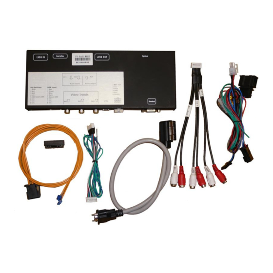
• Full plug and play multimedia interface
• 2 AV-inputs with separate IR-control-channels
• Integrated into vehicle infotainment
• control of 2 after-market devices by factory navigation buttons (e.g. DVD-player,
DVD-changer, USB/iPod devices, ...)
• after-market rear-view camera input
• compatible with factory rear-view camera
• automatic switching to rear-view camera input
• RGB-input for after-market navigation
• video-in-motion for fed in video signal
• PAL/NTSC input compatible
Version 19.10.2012
C2-MMI2G-x
Advertisement
Table of Contents

Related Manuals for Caraudio-Systems c.LOGiC C2-MMI2G Series


Summary of Contents for Caraudio-Systems c.LOGiC C2-MMI2G Series
- Page 1 c.LOGiC Interface C2-MMI2G-x Compatible with Audi MMI 2G navigation systems Product features • Full plug and play multimedia interface • 2 AV-inputs with separate IR-control-channels • Integrated into vehicle infotainment • control of 2 after-market devices by factory navigation buttons (e.g. DVD-player, DVD-changer, USB/iPod devices, …) •...
-
Page 2: Table Of Contents
Contents 1. Prior to installation 1.1. Delivery contents 1.2. Check compatibility of vehicle and accessories 1.3. Dip-switch settings 1.3.1. Enabling the interface’s video inputs (dip 1-3) 1.3.2. Rear-view camera settings (dip 5) 2. Connection schema- 3. Installation 3.1. Connections to the factory CD-changer 3.2. -
Page 3: Prior To Installation
Legal Information By law, watching moving pictures while driving is prohibited, the driver must not be distracted. We do not accept any liability for material damage or personal injury resulting, directly or indirectly, from installation or operation of this product. This product should only be used while standing or to display fixed menus or rear-view-camera video when the vehicle is moving, for example the MP3 menu for DVD upgrades. -
Page 4: Check Compatibility Of Vehicle And Accessories
1.2. Check compatibility of vehicle and accessories Requirements Vehicle A4 (B8/8K from early 2008), A5 (8T), A6 (4F), A8 (4D/4E), Q7 (4L) Navigation Audi MMI 2. generation Limitations Software version Only possible for MMI 2G with minimum software version 42.40. Note: Prerequisite for the faultless functioning of the interface is at least minimum software version 42.40. -
Page 5: Rear-View Camera Settings (Dip 5)
1.1.2. Rear-view camera settings (dip 5) Depending on whether no camera, after-market camera or factory camera shall be used, dip 5 must use different settings. Rear-view If set to OFF, the interface switches to factory LVDS picture when the Dip 5 camera type reverse gear is engaged to display factory rear-view camera or None... -
Page 6: Connection Schema
2. Connection schema Version 19.10.2012 C2-MMi2G-x... -
Page 7: Installation
3. Installation Switch off ignition and disconnect the vehicle’s battery! The interface needs a permanent 12V source. If according to factory rules disconnecting the battery is to be avoided, it is usually sufficient to put the vehicle is sleep-mode. In case the sleep-mode does not show success, disconnect the battery with a resistor lead. -
Page 8: Connections To The Factory Monitor Control-Box
3.2. Connections to the factory monitor control-box Connect the interface LVDS cable to the video-interface. Remove the female 22pin Mitsumi LVDS connector from the rear of the factory monitor control-box and connect it to the male 22pin Mitsumi LVDS connector of the video-interface. -
Page 9: Connecting Optical Ring
3.3. Connecting optical ring Remove the black MOST®-connector which contains the optical leads from the rear of the factory CD-changer. Remove the optical insert from the black connector. Remove the vehicle harness’ optical output lead (see arrows on MOST®-connector). With the included optical bridge, connect the removed vehicle harness’ optical output lead to the optical output lead of the interface’s optical ring (see arrows on MOST®-connector). -
Page 10: Av-Source(S)
3.4.1. AV-source(s) The c.LOGiC interface has the possibility to connect and remotely control by navigation buttons up to 2 pre-programmed devices. The device list in the device control table (appendix A) shows the pre-programmed remote channels and the related IR-control cables STA-xxx which must be ordered separately for the control of the device. -
Page 11: Installing Av-Source's Ir-Sensor Additionally
Audio pins Definition Audio input signal R/L of source IN2 Audio input signal R/L of source IN1 Audio output signal R/L Ground No function Note: When switching the video interface from video-IN1 to video-IN2, the at the integrated audio switch connected audio signal will also automatically be switched. 3.4.2. -
Page 12: After-Market Navigation
3.4.4. After-market navigation Connect female 8pin connector of the RGB cable to the male 8pin connector of the video-interface. The loose grey and the loose green wire have no function and have to be isolated. Connect male 6pin connector of the RGB cable to the after-Market navigation. The loose blue wire has no function and has to be isolated. -
Page 13: Operation
4. Operation 4.1. Video-in-motion function The video-in-motion function for the fed in video-signal is activated permanently without disturbing the navigation performance. 4.2. Selecting the c.LOGiC as current AV-source After installation the c.LOGiC is identified as factory CD-changer and is displayed as virtual (second) CD-changer in the “CD/TV” and accordingly the “MEDIA”... -
Page 14: Device Control
4.3. Device control After selecting the c.LOGiC as current AV-source it is possible to control the 2 fix pre-programmed devices by the knob of the left panel of the steering wheel. The display of the FIS shows the available functions among each other (first for AV1 and under it for AV2) in the CD-changer menu. -
Page 15: Technical Support
7. Technical support Caraudio-Systems Vertriebs GmbH manufacturer/distribution In den Fuchslöchern 3 D-67240 Bobenheim-Roxheim Email support@caraudio-systems.de Legal disclaimer: Mentioned company and trademarks, as well as product names/codes are registered trademarks ® of their corresponding legal owners. Version 19.10.2012 C2-MMi2G-x...
Need help?
Do you have a question about the c.LOGiC C2-MMI2G Series and is the answer not in the manual?
Questions and answers