
Related Manuals for Caraudio-Systems v.LOGiC Intelligent Solution V5-NTG46


Summary of Contents for Caraudio-Systems v.LOGiC Intelligent Solution V5-NTG46
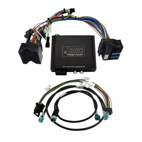
- Page 1 v.LOGiC Intelligent Solution Interface V5-NTG46 compatible with Mercedes Benz vehicles with COMAND Online NTG4.5 navigation and Audio20 NTG45 system with 4pin HSD LVDS connector Version 18.11.2016 V5-NTG46...
- Page 2 Product features Interactive lane lines Control by factory infotainment Own on-screen display and setup 2 trigger outputs (+12V max. 1A), separately adjustable switching events (CAN, ACC, rear-view camera, reverse gear) Rear-view camera input Front camera input ...
-
Page 3: Table Of Contents
Contents 1. Prior to Installation 1.1. Delivery contents 1.2. Check compatibility of vehicle and accessories 1.3. Setting the dip switches of the interface-box V5C-M613 1.4. LED’s of the interface-box V5C-M613 2. Connection schema 3. Installation 3.1. Connecting interface-box and harnesses 3.2. -
Page 4: Prior To Installation
Legal Information By law, watching moving pictures while driving is prohibited, the driver must not be distracted. We do not accept any liability for material damage or personal injury resulting, directly or indirectly, from installation or operation of this product. This product should only be used while standing or to display fixed menus or rear-view-camera video when the vehicle is moving, for example the MP3 menu for DVD upgrades. -
Page 5: Check Compatibility Of Vehicle And Accessories
1.2. Check compatibility of vehicle and accessories Requirements Vehicle Mercedes Benz with 6”/ 7“ monitor and 4pin HSD LVDS connector Device COMAND Online NTG4.5, Audio20 NTG4.5 1.3. Setting the dip switches of the interface-box V5C-M613 Dip 1 on the back of the interface-box V5C-M613 is used to set the monitor type. Device Dip 1 COMAND Online NTG4.5... -
Page 6: Connection Schema
2. Connection schema Interface-box V5C-M613 REAR LVDS cable CAB-HSD-DD075-O LVDS cable Back of CAB-HSD-MR-060-OZ head unit 4-Pin HSD LVDS female vehicle harness Interface-box V5C-M613 FRONT +12V Quadlock female vehicle harness Ground CAN (2) Rear-view camera CAN (1) V5C-UNI01 harness Front camera +12V switching outputs Rear gear signal... -
Page 7: Installation
3. Installation Switch off ignition and disconnect the vehicle’s battery! The interface needs a permanent 12V source. If according to factory rules disconnecting the battery is to be avoided, it is usually sufficient to put the vehicle is sleep-mode. In case the sleep-mode does not show success, disconnect the battery with a resistor lead. - Page 8 Cut the CAN bus wires of the vehicle harness and connect them in series according to the assignment (see below) with the CAN bus wires from the V5C-UNI01 harness. Connect red wire with +12V (pin 15) and black wire with ground (pin 12). Connect female 12pin AMP connector of the harness V5C-UNI01 to the front site of the V5C-M613 interface box.
-
Page 9: Lvds Connection
3.2. LVDS connection Interface-box V5C-M613 REAR LVDS cable CAB-HSD-DD075-O LVDS cable Back of CAB-HSD-MR-060-OZ head unit 4-Pin HSD LVDS female vehicle harness Connect the female 4pin HSD LVDS connector of the LVDS cable CAB-HSD-DD075-O to the male 4pin HSD LVDS connector (LVDS-IN) on the rear of the interface-box V5C-M613. -
Page 10: After-Market Front Camera
3.2.1. After-market front camera 3.2.1.1. Connection to the after-market front camera Interface-box V5C-M613 FRONT V5C-UNI01 harness Front camera +12V camera Power Out 1 (max. 1A) power Connect the video RCA of the after-market front camera to the female RCA connector “FRONT CAM”... -
Page 11: Settings For Connecting An After-Market Front Camera
3.2.1.2. Settings for connecting an after-market front camera You have to configure some settings in the OSD-menus INPUTS and MISC if you want to connect an after-market front camera (Operation of the OSD: see chapter “OSD-Operation”). OSD-menu Menu item Setting Explication Keine Frontkamera angeschlossen INPUT... -
Page 12: Rear-View Camera
3.2.2. After-market rear-view camera 3.2.2.1. Connection to the after-market rear-view camera Interface-box V5C-M613 FRONT V5C-UNI01 harness Rear-view camera +12V camera Power Out 2 (max. 1A) power Rear gear signal input (+12V) Connect the video RCA of the after-market rear-view camera to the female RCA connector “REAR CAM”... -
Page 13: Settings For Connecting An After-Market Rear-View Camera
3.2.2.2. Settings for connecting an after-market rear-view camera You have to configure some settings in the OSD-menus INPUT and OPTION if you want to connect an after-market rear-view camera (Operation of the OSD: see chapter “OSD- Operation”). OSD-menu Menu item Setting Explication No rear-view camera connected... -
Page 14: Configurable Trigger Outputs
3.2.3. Configurable trigger outputs Interface-box V5C-M613 FRONT +12V switching outputs Power Out 1 (max. 1A) Power Out 2 (max. 1A) V5C-UNI01 harness You can configure the both +12V trigger outputs separately. The pink wire is POWER OUT 1 and the green wire is POWER OUT 2. Note: You can configure the both trigger outputs in the OSD-menu OPTION separately (Operation of the OSD: see chapter “OSD-Operation”). -
Page 15: Interactive Lane Lines
3.3. Interactive lane lines You have to configure some settings in the OSD-menu OPTION if you want to activate interactive lane lines (Operation of the OSD: see chapter “OSD-Operation”). OSD-menu Menu item Setting Explication Interactive lane lines deactivated RVC LINES Interactive lane lines activated A/B/C/CLA/CLS/ OPTION... -
Page 16: Operation
4. Operation 4.1. OSD – On-screen display You can change the basic configurations of the interface in the OSD (on screen display). 4.1.1. OSD – Operation You can control the OSD by steering wheel buttons. Set the "radio level" in instrument cluster before you start the OSD control. -
Page 17: Osd - Additional Setting Options
4.1.2. OSD – Additional setting options The following settings in the OSD-menus OPTION and OSD can be configured over and above the described settings in this manual (Operation of the OSD: see chapter “OSD-Operation”): OSD-menu Menu item Setting Explication POS. X 0-xxx Horizontal position of the OSD POS. -
Page 18: Specifications
Front camera Female input update-connector Mini USB 7. Technical Support Caraudio-Systems Vertriebs GmbH manufacturer/distribution In den Fuchslöchern 3 D-67240 Bobenheim-Roxheim email support@caraudio-systems.de Legal disclaimer: Mentioned company and trademarks, as well as product names/codes are registered trademarks ® of their corresponding legal owners.
Need help?
Do you have a question about the v.LOGiC Intelligent Solution V5-NTG46 and is the answer not in the manual?
Questions and answers