
Related Manuals for WAGO 750-563


Summary of Contents for WAGO 750-563
- Page 1 Fieldbus Independent I/O Modules 2 AO 0/4-20mA / 6-18V DC 16 Bit 750-563 Manual Version 1.0.0...
- Page 2 • General Copyright © 2008 by WAGO Kontakttechnik GmbH & Co. KG All rights reserved. WAGO Kontakttechnik GmbH & Co. KG Hansastraße 27 D-32423 Minden Phone.: +49 (0) 571/8 87 – 0 Fax: +49 (0) 571/8 87 – 1 69 E-Mail: info@wago.com...
-
Page 3: Table Of Contents
Number Notation..................6 Safety Notes ..................... 7 Scope ......................5 2 I/O Modules ....................8 Analog Output Modules ................8 2.1.1 750-563 [2 AO 0/4-20mA / 6-18V DC 16 Bit] ........8 2.1.1.1 View....................8 2.1.1.2 General Description ................ 8 2.1.1.3 Connecting Elements .............. - Page 4 • Content 2.1.1.10 Technische Daten................45 2.1.1.11 Fieldbus-Specific Behavior............47 2.1.1.11.1 Default Mapping ..............47 2.1.1.11.2 Mapping for Couplers/Controllers with Word-Alignment ..47 WAGO-I/O-SYSTEM 750 I/O Modules...
-
Page 5: Important Comments
WAGO Kontakttechnik GmbH & Co. KG declines all liability resulting from improper action and damage to WAGO products and third party products due to non-observance of the information contained in this manual. -
Page 6: Symbols
Additional Information References for additional literature, manuals, data sheets and web pages. 1.3 Number Notation Number Code Example Note Decimal normal notation Hexadecimal 0x64 C notation Binary '100' within inverted commas, '0110.0100' nibble separated with dots WAGO-I/O-SYSTEM 750 I/O Modules... -
Page 7: Safety Notes
1.5 Scope This manual describes the Analog Output Module 750-563 2 AO 0/4-20mA / 6-18V DC 16 Bit of the modular WAGO-I/O- SYSTEM 750. Handling, assembly and start-up are described in the manual of the Fieldbus Coupler. -
Page 8: O Modules
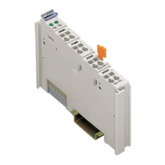
Fig. 2.1.1-1: View g056300e 2.1.1.2 General Description The 750-563 analog output module generates output currents in the range from 0/4 ... 20 mA or output voltages in the range from 6 ... 18 V for the field area. The module has two short circuit-proof output channels and enables the direct cabling of two 2-line actuators on the connections AO 1 and ground or AO2 and ground. - Page 9 750-563 [2 AO 0/4-20mA / 6-18V DC 16 Bit] • 9 General Description The readiness for operation and the disturbance-free I/O module communication of the module is indicated with one green function LED per channel. An overload or a short circuit of an output is indicated by one red error LED per channel.
-
Page 10: Connecting Elements
10 • 750-563 [2 AO 0/4-20mA / 6-18V DC 16 Bit] Connecting Elements 2.1.1.3 Connecting Elements Connection Name Function A1+ A2+ Analog output 1 +AO 2 +AO 1 Positive sense connection for S1+ S2+ analog output 1 Negative sense connection... -
Page 11: Schematic Diagram
750-563 [2 AO 0/4-20mA / 6-18V DC 16 Bit] • 11 Schematic Diagram 2.1.1.6 Schematic Diagram 0 ... 20 mA +AO 2 +AO 1 Logic 6 ... 18 V 100 nF Function Error +Sense AO 1 +Sense AO 2 +24 V... -
Page 12: Control And Status Bytes
12 • 750-563 [2 AO 0/4-20mA / 6-18V DC 16 Bit] Process Image 2.1.1.7.2 Control and Status Bytes Controlbyte C0 Bit 7 Bit 6 Bit 5 Bit 4 Bit 3 Bit 2 Bit 1 Bit 0 Reg_Com Reg_Com Process data communication... - Page 13 750-563 [2 AO 0/4-20mA / 6-18V DC 16 Bit] • 13 Process Image Controlbyte C1 Bit 7 Bit 6 Bit 5 Bit 4 Bit 3 Bit 2 Bit 1 Bit 0 Reg_Com Reg_Com Process data communication Reserved Statusbyte S1 Bit 7...
-
Page 14: Process Values
14 • 750-563 [2 AO 0/4-20mA / 6-18V DC 16 Bit] Process Image 2.1.1.7.3 Process Values Data format 0 ... 65535 Manufacturer calibration, without user scaling Numeric value 6 ... 18 V, [U ] = V hexadecimal decimal 0000 3FFF... - Page 15 750-563 [2 AO 0/4-20mA / 6-18V DC 16 Bit] • 15 Process Image Numeric formats 0 mA 20 mA Display 4 mA 20 mA 18 V 0x0000 0x7FFF 0x8000 0xFFFF 0 ... 65535 32767 32768 65535 0x8000 0xFFFF 0x0001 0x7FFF...
-
Page 16: Function Description
16 • 750-563 [2 AO 0/4-20mA / 6-18V DC 16 Bit] Function Description 2.1.1.8 Function Description The conversion algorithm takes into account all calculation and evaluation steps of the process data up to the analog output value. The individual steps will be explained in this chapter. -
Page 17: Step 2 - Y 1 User Scaling
750-563 [2 AO 0/4-20mA / 6-18V DC 16 Bit] • 17 Function Description 2.1.1.8.2 Step 2 – Y User Scaling The value for Y is generated with the user scaling if this is approved through bit 0 of the register 32. The value X serves as input value for the user scaling. -
Page 18: Step 3 - Y
18 • 750-563 [2 AO 0/4-20mA / 6-18V DC 16 Bit] Function Description 2.1.1.8.3 Step 3 – Y Conversion of the Data Format In this step, the value Y determined through the configured data format is converted into the DAC format, leading sign-less 16 bit integer. The context... -
Page 19: Dac Calibration
750-563 [2 AO 0/4-20mA / 6-18V DC 16 Bit] • 19 Function Description 2.1.1.8.5 Step 5 – Y Calibration This level serves to calibrate an analog output range to the process data value range. AS parameter for the calibration, the module will only transmit the basic value for the minimum value of the analog output range as offset. -
Page 20: Parameter Setting
20 • 750-563 [2 AO 0/4-20mA / 6-18V DC 16 Bit] Parameter Setting 2.1.1.9 Parameter Setting 2.1.1.9.1 Register Assignment The following tables display the assignments and factory settings for the individual registers. The factory settings are the same for both channels. - Page 21 750-563 [2 AO 0/4-20mA / 6-18V DC 16 Bit] • 21 Parameter Setting Register Function Memory Access Factory setting Mode setting EEPROM 0x8016 Bit 0: activation of the user scaling 0: * User scaling (register 33 and register 34) is not active.
- Page 22 22 • 750-563 [2 AO 0/4-20mA / 6-18V DC 16 Bit] Parameter Setting Register Function Memory Access Factory setting Bit 9: Substitute value after I/O module timeout 0: * Manufacturer substitution value User substitute value Bits 10, 11: Behavior after I/O module timeout The reaction depends on register 32, bit 2.
- Page 23 750-563 [2 AO 0/4-20mA / 6-18V DC 16 Bit] • 23 Parameter Setting Setting the numeric display (cf. register 32, bit 3, and bit 6) 0 mA 20 mA Bit 6 Bit 3 Display 4 mA 20 mA 18 V...
- Page 24 24 • 750-563 [2 AO 0/4-20mA / 6-18V DC 16 Bit] Parameter Setting Register Function Memory Access Factory setting User calibration gain 0xXXXX 16 bit fixed point value without leading sign. The user calibration is active if bit 1 is not set in register 32.
-
Page 25: Data Structures
750-563 [2 AO 0/4-20mA / 6-18V DC 16 Bit] • 25 Parameter Setting 2.1.1.9.2 Data Structures 2.1.1.9.2.1 Configuration Concept In addition to direct register access, the registers 32, 33 ... 37, and 41 ... 42 are also accessible via addresses of the parameter channel. The relationship between these registers and the addresses of the parameter channel are described in Chapter 4.6. - Page 26 26 • 750-563 [2 AO 0/4-20mA / 6-18V DC 16 Bit] Parameter Setting Register or Parameter channel communcation Write Register X, Channel Y Placing new date Operation mode in data base MA MA ? Placing new date Operation mode in data base MB...
-
Page 27: Parameterization Via Register Communication
• 27 Parameter Setting 2.1.1.9.3 Parameterization via Register Communication The operating mode and the parameters for the 750-563 module can be set using the register communication. The values for channel 1 are set via control and status bytes C0/S0 for the addressing and via data bytes D0 and D1 for the transmission of the values to be set. -
Page 28: Register Assignment
28 • 750-563 [2 AO 0/4-20mA / 6-18V DC 16 Bit] Parameter Setting 2.1.1.9.3.1 Register Assignment Control / Channel Function Register Data bytes status byte Manufacturer calibration offset C0/S0 D0/D1 Manufacturer calibration gain C0/S0 D0/D1 Manufacturer substitution value C0/S0 D0/D1... -
Page 29: Control And Status Byte At Register Communication
750-563 [2 AO 0/4-20mA / 6-18V DC 16 Bit] • 29 Parameter Setting 2.1.1.9.3.2 Control and Status Byte at Register Communication The following tables show the assignment of the control and status bytes for register communication. With the bits 0 ... 5 and 7 in the respective status byte, the register communication is acknowledged by the I/O module. -
Page 30: Parameterization Via The Parameter Channel
30 • 750-563 [2 AO 0/4-20mA / 6-18V DC 16 Bit] Parameter Setting 2.1.1.9.4 Parameterization via the Parameter Channel In addition to the direct register access, it is possible to access registers of the user range via the addresses of the parameter channel. -
Page 31: Register Structure
750-563 [2 AO 0/4-20mA / 6-18V DC 16 Bit] • 31 Parameter Setting 2.1.1.9.4.2 Register Structure 2.1.1.9.4.2.1 Parameter Data (Register 56) Register 56 contains the parameter data to be read or written. Depending on the access type, either the I/O module (read parameters) or the fieldbus coupler (write parameters) will write data to the register. - Page 32 32 • 750-563 [2 AO 0/4-20mA / 6-18V DC 16 Bit] Parameter Setting Parameter Value range Meaning A0 … A7 0 ...255 Word address of the parameter to be read / to be written. TGL_MS 0, 1 Toggle bit to release new instructions from the application to the module.
-
Page 33: Write/Read Process
750-563 [2 AO 0/4-20mA / 6-18V DC 16 Bit] • 33 Parameter Setting 2.1.1.9.4.3 Write/Read Process Request (application) Parameter Value Meaning TGL_MS != TGL_SM Initiate instruction PRM_RW Read access Write access MORE_PRM Parameter data transmission is completed with the currently-transmitted parameter. -
Page 34: Examples
34 • 750-563 [2 AO 0/4-20mA / 6-18V DC 16 Bit] Parameter Setting 2.1.1.9.4.4 Examples Example 1: Writing The value 2300 (dec.) should be written to parameter channel address 8 (corresponds to register 36, offset user calibration, channel 1). 1. Enter the value 2300 in register 56 2. -
Page 35: Parameterization Via Wago-I/O-Check
750-563 [2 AO 0/4-20mA / 6-18V DC 16 Bit] • 35 Parameter Setting 2.1.1.9.5 Parameterization via WAGO-I/O-CHECK The module can be parameterized easily with the start-up tool WAGO-I/O- CHECK. 2.1.1.9.5.1 User Interface The user interface of the 2-channel output module parameterizing dialog is divided into the following areas. - Page 36 36 • 750-563 [2 AO 0/4-20mA / 6-18V DC 16 Bit] Parameter Setting 2.1.1.9.5.1.1 Title Bar The position of the module within the mode as well as its name, item, and version number are displayed on the title bar of the parameterizing dialog.
- Page 37 750-563 [2 AO 0/4-20mA / 6-18V DC 16 Bit] • 37 Parameter Setting 2.1.1.9.5.1.3 Navigation Bar With the navigation bar on the left side, you can change between the channels of the module. Fig. 2.1.1-9: Navigation between channels You can select from among the following menu items:...
- Page 38 38 • 750-563 [2 AO 0/4-20mA / 6-18V DC 16 Bit] Parameter Setting 2.1.1.9.5.1.4 Input and Selection Fields This area of the 2-channel output module consists of 3 pages. On the Settings and Offset/Gain pages, you can change and set the parameters.
- Page 39 750-563 [2 AO 0/4-20mA / 6-18V DC 16 Bit] • 39 Parameter Setting The following parameters can be changed and loaded onto the module. Description Input/Selection Description Operation Mode 0 ... 20 mA Selection of the operating mode of the device 4 ...
- Page 40 40 • 750-563 [2 AO 0/4-20mA / 6-18V DC 16 Bit] Parameter Setting Description Input/Selection Description User Power-On Value 0* ... +65535 Setting of the user substitute value WAGO Power-On 0* ... +65535 Setting of the manufacturer Value substitute value...
- Page 41 750-563 [2 AO 0/4-20mA / 6-18V DC 16 Bit] • 41 Parameter Setting The following parameters can be changed and loaded onto the module. Description Input/Selection Description User Scaling Off* Activation of the user scaling Offset 0* ... +65535 Setting of the offset of the user...
- Page 42 42 • 750-563 [2 AO 0/4-20mA / 6-18V DC 16 Bit] Parameter Setting 2.1.1.9.5.1.4.3 Process data This page displays the process value and the status messages of the module. Fig. 2.1.1-12: Process data Under "Process Value" the value can be set as follows:...
- Page 43 750-563 [2 AO 0/4-20mA / 6-18V DC 16 Bit] • 43 Parameter Setting The display field offers the following diagnostic possibilities: Name Input/ Description Selection Common Collective Fault No group error. Group error present. Output Error Overload No output driver error (LAST).
-
Page 44: Parameterization Via Gsd
44 • 750-563 [2 AO 0/4-20mA / 6-18V DC 16 Bit] Parameter Setting 2.1.1.9.5.1.5 Status Indication Status messages are output on the status indicator in the lower area of the parameterizing dialog. Fig. 2.1.1-13 Status indication 2.1.1.9.6 Parameterization via GSD With use of a Profibus fieldbus system, the module can be parameterized via the presetting in the GSD. - Page 45 750-563 [2 AO 0/4-20mA / 6-18V DC 16 Bit] • 45 Technische Daten 2.1.1.10 Technische Daten Ausgänge No. of outputs Connection type 2 or 4-wire technology Output voltage or output current (switchable) 0 V ... 18 V (-0.5 V ... +18.5 V) 0 mA ...
- Page 46 46 • 750-563 [2 AO 0/4-20mA / 6-18V DC 16 Bit] Technische Daten Standards and directives (see section 2.2 in manual on coupler/controller) EMC CE Immunity to interference acc. to EN 61131-2 (2003) EMC CE emission of interference acc. to EN 61131-2 (2003)
- Page 47 750-563 [2 AO 0/4-20mA / 6-18V DC 16 Bit] • 47 Fieldbus-Specific Behavior 2.1.1.11 Fieldbus-Specific Behavior 2.1.1.11.1 Default Mapping Byte Input data Output data Status byte 0 Control byte 0 Not used Output data word 1 (LSB) Not used Output data word 1 (MSB)
- Page 48 WAGO Kontakttechnik GmbH & Co. KG Postfach 2880 • D-32385 Minden Hansastraße 27 • D-32423 Minden Telefon: 05 71/8 87 – 0 Telefax: 05 71/8 87 – 1 69 E-Mail: info@wago.com Internet: http://www.wago.com...
Need help?
Do you have a question about the 750-563 and is the answer not in the manual?
Questions and answers