Table of Contents
Advertisement
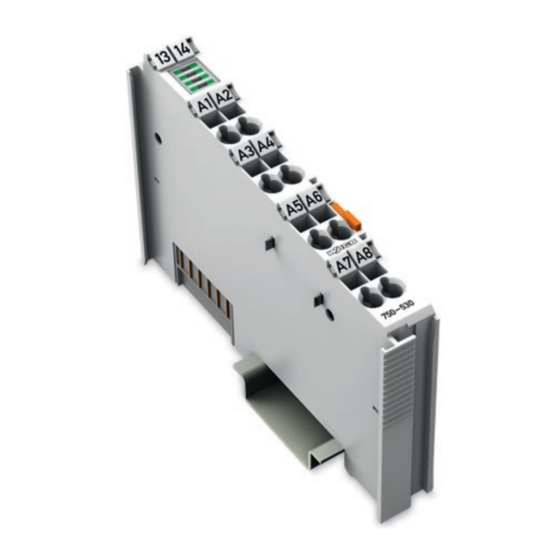
WAGO-I/O-SYSTEM 750
Pos : 2 /D okumentati on allgemein/Ei nband/Ei nband H andbuch - Fronts eite 2015 - mit Doc Variabl en (Standar d) @ 9\mod_1285229289866_0.doc x @ 64941 @ @ 1
Manual
750-530(/xxx-xxx)
8DO 24V DC 0.5A
8-Channel Digital Output Module 24 VDC; Short-
circuit Protected; High-side Switching
Version 1.2.0
Pos : 3 /Alle Serien (Allgemeine M odul e)/Hinweise z ur Dokumentation/Impres sum für Standardhandbüc her - allg. Angaben, Ansc hriften, Tel efonnummer n und E-Mail-Adres sen @ 3\mod_1219151118203_21.doc x @ 21060 @ @ 1
Advertisement
Chapters
Table of Contents

Related Manuals for WAGO 750-530


Summary of Contents for WAGO 750-530
- Page 1 WAGO-I/O-SYSTEM 750 Pos : 2 /D okumentati on allgemein/Ei nband/Ei nband H andbuch - Fronts eite 2015 - mit Doc Variabl en (Standar d) @ 9\mod_1285229289866_0.doc x @ 64941 @ @ 1 Manual 750-530(/xxx-xxx) 8DO 24V DC 0.5A 8-Channel Digital Output Module 24 VDC; Short- circuit Protected;...
- Page 2 WAGO-I/O-SYSTEM 750 750-530 8DO 24V DC 0.5A © 2015 by WAGO Kontakttechnik GmbH & Co. KG All rights reserved. WAGO Kontakttechnik GmbH & Co. KG Hansastraße 27 D-32423 Minden Phone: +49 (0) 571/8 87 – 0 Fax: +49 (0) 571/8 87 – 1 69 E-Mail: info@wago.com...
-
Page 3: Table Of Contents
2.1.1 Subject to Changes ................9 2.1.2 Personnel Qualifications ............... 9 2.1.3 Use of the WAGO-I/O-SYSTEM 750 in Compliance with Underlying Provisions ..................... 9 2.1.4 Technical Condition of Specified Devices ......... 10 Safety Advice (Precautions) ..............11 Device Description ..................13 View ...................... - Page 4 Table of Contents WAGO-I/O-SYSTEM 750 750-530 8DO 24V DC 0.5A 7.2.1 General Structure ................34 Use in Hazardous Environments .............. 35 Marking Configuration Examples ............36 8.1.1 Marking for Europe According to ATEX and IEC-Ex ...... 36 8.1.2 Marking for America According to NEC 500 ........41 Installation Regulations ................
-
Page 5: Notes About This Documentation
Pos : 10 /Serie 750 ( WAGO-I/O-SYST EM)/Hi nweis e z ur D okumentati on/Gültigkeits bereic h/Gültig keits ber eich Dokumentation Bus kl emme 750- xxxx, Standar dversi on und aufgelistete Varianten @ 14\mod_1358944038682_21.doc x @ 109354 @ @ 1... -
Page 6: Symbols
Notes about this Documentation WAGO-I/O-SYSTEM 750 750-530 8DO 24V DC 0.5A Pos : 14.2 /Dokumentation allgemei n/Glieder ungs elemente/---Seitenwechs el--- @ 3\mod_1221108045078_0.doc x @ 21810 @ @ 1 Pos : 14.3 /All e Seri en ( Allgemei ne Module)/Ü bers chriften für alle Serien/Hinweis e z ur Dokumentation/Symbol e - Ü bersc hrift 2 @ 13\mod_1351068042408_21.doc x @ 105270 @ 2 @ 1 Symbols Pos : 14.4.1 /All e Serien ( Allgemei ne Module)/Wic htige Erläuterungen/Sicherheits- und sons tige Hinweis e/Gefahr/Gefahr: _War nung vor Personenschäden allgemei n_ - Erl äuter ung @ 13\mod_1343309450020_21.doc x @ 101029 @ @ 1... - Page 7 WAGO-I/O-SYSTEM 750 Notes about this Documentation 750-530 8DO 24V DC 0.5A Additional Information: Refers to additional information which is not an integral part of this documentation (e.g., the Internet). Pos : 14.5 /Dokumentation allgemei n/Glieder ungs elemente/---Seitenwechs el--- @ 3\mod_1221108045078_0.doc x @ 21810 @ @ 1 Manual Version 1.2.0...
-
Page 8: Number Notation
WAGO-I/O-SYSTEM 750 750-530 8DO 24V DC 0.5A Pos : 14.6 /All e Seri en ( Allgemei ne Module)/Hi nweis e zur D okumentati on/Dars tellung der Zahlens ys teme - Ü berschrift 2 und Inhal t @ 3\mod_1221059454015_21.doc x @ 21711 @ 2 @ 1... -
Page 9: Important Notes
PLC programming. Pos : 17.5 /Serie 750 (WAGO-I/O-SYST EM)/Wic htige Erläuterungen/Bes timmungsgemäß e Verwendung Bes ti mmungsgemäße Verwendung 750-xxxx - Ü berschrift 3 und Inhal t @ 3\mod_1224064151234_21.doc x @ 24070 @ 3 @ 1 2.1.3... -
Page 10: Technical Condition Of Specified Devices
WAGO-I/O-SYSTEM 750 750-530 8DO 24V DC 0.5A Appropriate housing (per 94/9/EG) is required when operating the WAGO-I/O- SYSTEM 750 in hazardous environments. Please note that a prototype test certificate must be obtained that confirms the correct installation of the system in a housing or switch cabinet. -
Page 11: Safety Advice (Precautions)
Pos : 17.10.2 /Serie 750 ( WAGO-I/O- SYST EM)/Wic htig e Erl äuter ung en/Sic her hei ts- und s onstige Hi nweise/Gefahr/Gefahr: Ei nbau 0750- xxxx nur i n Gehäus en, Sc hränken oder el ektrisc hen Betriebsräumen! @ 6\mod_1260180556692_21.doc... - Page 12 Important Notes WAGO-I/O-SYSTEM 750 750-530 8DO 24V DC 0.5A Do not use any contact spray! Do not use any contact spray. The spray may impair contact area functionality in connection with contamination. Pos : 17.11.5 /Alle Serien (Allgemeine D okumente) (Allgemeine M odul e)/Wichtige Erläuter ungen/Sic herheits hinweise/Ac htung/Ac htung: Verpol ung ver mei den! @ 6\mod_1260184045744_21.doc x @ 46767 @ @ 1...
-
Page 13: Device Description
I/O modules via spring-formed power jumper contacts. Pos : 20.12 /Serie 750 ( WAGO-I/O-SYST EM)/Wichtig e Erl äuter ung en/Sic her hei ts- und s onstige Hinweise/Ac htung/Ac htung: Maxi maler Str om Leis tungs kontakte 10 A @ 3\mod_1226499143500_21.doc x @ 25029 @ @ 1 Manual Version 1.2.0... - Page 14 Pos : 20.15 /Serie 750 ( WAGO-I/O-SYST EM)/Gerätebeschr eibung/Ei nleitung/Einsatzbereic h/Einsatzbereic h 750- xxxx alle Koppler/C ontroll er ohne Ei nsc hränkung @ 3\mod_1232541691906_21.doc x @ 26522 @ @ 1 The I/O module 750-530 can be used with all fieldbus couplers/controllers of the WAGO-I/O-SYSTEM 750.
-
Page 15: View
Pos : 23 /Serie 750 ( WAGO-I/O-SYST EM)/Ger ätebesc hrei bung/Ansic ht/Digitalausgangs kl emmen/Ansic ht 750-0530 @ 11\mod_1322217539668_21.doc x @ 83727 @ @ 1 Figure 1: View Pos : 24 /Serie 750 ( WAGO-I/O-SYST EM)/Ger ätebesc hrei bung/Ansic ht/Ansic ht C ageCl amp® _Leg ende mit LED s @ 15\mod_1370867188922_21.doc x @ 122225 @ @ 1 Table 4: Legend for Figure “View”... -
Page 16: Connectors
Pos : 28.3 /Serie 750 (WAGO-I/O-SYST EM)/Wic htige Erläuterungen/Sicherheits- und sonstig e Hinweis e/Achtung/Achtung: ESD - Auf g ute Erdung der U mgebung ac hten! @ 7\mod_1266318538667_21.doc x @ 50708 @ @ 1 Ensure that the environment is well grounded! The devices are equipped with electronic components that may be destroyed by electrostatic discharge. -
Page 17: Power Jumper Contacts/Field Supply
Pos : 31.3 /Serie 750 (WAGO-I/O-SYST EM)/Ger ätebesc hrei bung/Ansc hl üsse/Leistungs kontakte 2 LK (Mess er/Leis tungs kontakte 2 LK (Messer /Feder) - Abbil dung, einfac he Breite - Standard @ 15\mod_1367500700037_21.doc x @ 118396 @ @ 1 Figure 3: Power Jumper Contacts Pos : 31.4 /Serie 750 (WAGO-I/O-SYST EM)/Ger ätebesc hrei bung/Ansc hl üsse/Leistungs kontakte 2 LK (Mess er/Leis tungs kontakte 2 LK (Messer /Feder) - Legende @ 15\mod_1371721352500_21.doc x @ 123710 @ @ 1... - Page 18 Device Description WAGO-I/O-SYSTEM 750 750-530 8DO 24V DC 0.5A Use supply modules for ground (earth)! The I/O module has no power jumper contacts for receiving and transmitting the earth potential. Use a supply module when an earth potential is needed for the subsequent I/O modules.
-
Page 19: Cage Clamp ® Connectors
CAGE CLAMP Connectors Pos : 34 /Serie 750 ( WAGO-I/O-SYST EM)/Ger ätebesc hrei bung/Ansc hl üss e/Digital ausg angs kl emmen/Anschl üss e 750- 05xx 8 DO 1- Leiter @ 11\mod_1322218240918_21.doc x @ 83734 @ @ 1 ® Figure 4: CAGE CLAMP Connectors ®... -
Page 20: Display Elements
Pos : 36 /All e Seri en (Allgemei ne Module)/Ü berschriften für alle Serien/Gerätebesc hreibung/Anz eigeel emente - Übersc hrift 2 @ 4\mod_1240984390875_21.doc x @ 31964 @ 2 @ 1 Display Elements Pos : 37 /Serie 750 ( WAGO-I/O-SYST EM)/Ger ätebesc hrei bung/Anz eigeelemente/Digitalausgangs kl emmen/Anz eigeelemente 750-05xx 8 D O @ 11\mod_1322218413230_21.doc x @ 83738 @ @ 1 Figure 5: Display Elements Table 7: Legend for Figure “Display Elements”... -
Page 21: Schematic Diagram
Pos : 39 /All e Seri en (Allgemei ne Module)/Ü berschriften für alle Serien/Gerätebesc hreibung/Sc hematisches Sc haltbil d - Ü bersc hrift 2 @ 4\mod_1240984441312_21.doc x @ 31967 @ 2 @ 1 Schematic Diagram Pos : 40 /Serie 750 ( WAGO-I/O-SYST EM)/Ger ätebesc hrei bung/Schematisc he Sc haltbil der/Digitalausgangs klemmen/Schematisc hes Sc haltbil d 750-0530 @ 11\mod_1322219241981_21.doc x @ 83742 @ @ 1 Figure 6: Schematic Diagram Pos : 41 /D okumentation allgemei n/Glieder ungs elemente/---Seitenwechs el--- @ 3\mod_1221108045078_0.doc x @ 21810 @ @ 1... -
Page 22: Technical Data
Pos : 42 /All e Seri en (Allgemei ne Module)/Ü berschriften für alle Serien/Gerätebesc hreibung/Technisc he Daten - Ü berschrift 2 @ 3\mod_1232967587687_21.doc x @ 26924 @ 2 @ 1 Technical Data Pos : 43 /Serie 750 ( WAGO-I/O-SYST EM)/Ger ätebesc hrei bung/T echnisc he Daten/Digitalausgangs klemmen/T echnisc he Daten 750- 0530 @ 11\mod_1322219364548_21.doc x @ 83746 @ 3333 @ 1 3.5.1 Device Data Table 8: Technical Data ‒... -
Page 23: Connection Type
Pos : 46 /Serie 750 ( WAGO-I/O-SYST EM)/Ger ätebesc hrei bung/T echnisc he Daten/Kli matische U mg ebungs bedi ngungen/Technisc he Daten Klimat. U mgebungs bed. mi t erw. T emp. -20...+60°C /-40...+85°C für /025 @ 5\mod_1247658089120_21.doc... -
Page 24: Approvals
Pos : 50 /Serie 750 ( WAGO-I/O-SYST EM)/Ger ätebesc hrei bung/Z ulass ungen/Allgemei n/Z ulass ungen Bus kl emme 750- xxxx Allgemein, Standardversi on und all e Vari anten - Einl eitung @ 3\mod_1233911570312_21.doc x @ 27390 @ @ 1... -
Page 25: Table 16: Ship Approvals
750-530 8DO 24V DC 0.5A Pos : 59 /Serie 750 ( WAGO-I/O-SYST EM)/Ger ätebesc hrei bung/Z ulass ungen/Schiff/Z ulas sungen Bus klemme 750- xxxx Sc hiff, Standardversion und aufgelistete Vari anten - Einl eitung @ 16\mod_1376313495745_21.doc x @ 128461 @ @ 1... -
Page 26: Standards And Guidelines
Standards and Guidelines Pos : 64 /Serie 750 ( WAGO-I/O-SYST EM)/Ger ätebesc hrei bung/N ormen und Ric htlini en/EM V-Nor men Bus kl emme 750- xxxx, ohne Variantenang abe - Einl eitung @ 4\mod_1242803944015_21.doc x @ 33642 @ @ 1... -
Page 27: Process Image
Process Image Pos : 71 /Serie 750 ( WAGO-I/O-SYST EM)/Proz ess abbild Kl emmenbus /Hinweis: Prozes sabbildmapping abhängig von FBK/PFC, ohne Status-/C ontr olbyte @ 6\mod_1256126797251_21.doc x @ 43340 @ @ 1 Mapping of process data in the process image of fieldbus systems The representation of the process data of some I/O modules or their variants in the process image depends on the fieldbus coupler/controller used. -
Page 28: Mounting
I/O modules with fewer power contacts. Pos : 75.2 /Serie 750 (WAGO-I/O-SYST EM)/Wic htige Erläuterungen/Sicherheits- und sonstig e Hinweis e/Vorsic ht/Vorsicht: Verl etz ungsgefahr durc h s charfkantige M ess er kontakte! @ 6\mod_1256193279401_21.doc x @ 43414 @ @ 1 Risk of injury due to sharp-edged blade contacts! The blade contacts are sharp-edged. -
Page 29: Inserting And Removing Devices
Mounting 750-530 8DO 24V DC 0.5A Pos : 75.6 /Serie 750 (WAGO-I/O-SYST EM)/M ontieren/D emontieren/Geräte einfüg en und entfer nen - Ü berschrift 2 @ 3\mod_1231768483250_21.doc x @ 25950 @ 2 @ 1 Inserting and Removing Devices Pos : 75.7 /All e Seri en ( Allgemei ne Module)/Wic htige Erläuterungen/Sicherheits- und sons tige Hi nweis e/Ac htung/Achtung: Arbeiten an Ger äten nur s pannungsfr ei durc hführ en! @ 6\mod_1256193963573_21.doc x @ 43426 @ @ 1 Perform work on devices only if they are de-energized! Working on energized devices can damage them. -
Page 30: Removing The I/O Module
Mounting WAGO-I/O-SYSTEM 750 750-530 8DO 24V DC 0.5A Pos : 75.10 /Serie 750 ( WAGO-I/O-SYST EM)/Monti eren/D emonti eren/Bus kl emme entfer nen @ 4\mod_1239169375203_21.doc x @ 30334 @ 3 @ 1 5.2.2 Removing the I/O Module Remove the I/O module from the assembly by pulling the release tab. -
Page 31: Connect Devices
Connect Devices Pos : 78 /Serie 750 ( WAGO-I/O-SYST EM)/Ans chli eßen/Leiter an C AGE C LAM P ans chli eßen ( allgemei n) - Übersc hrift 2 und Text @ 3\mod_1225448660171_21.doc x @ 24928 @ 2 @ 1 ®... -
Page 32: Using Interference-Free Variants Of I/O Modules In Safety Related Applications
750-530 8DO 24V DC 0.5A Pos : 80.1 /Serie 750 (WAGO-I/O-SYST EM)/Eins atz in sicherheitsg erichteten Anwendung en/Ei nleitung - r üc kwir kungsfr eie Varianten @ 6\mod_1258973563064_21.doc x @ 44681 @ 1 @ 1 Using Interference-Free Variants of I/O Modules in Safety Related Applications The variant 750-530/xxx-8xx of the I/O module 750-530 (designation “... -
Page 33: Important Notes
750-530 8DO 24V DC 0.5A Pos : 80.4 /Serie 750 (WAGO-I/O-SYST EM)/Eins atz in sicherheitsg erichteten Anwendung en/Hi nweise zum Ei nsatz i n Sicherheits anwendungen @ 6\mod_1258974811438_21.doc x @ 44688 @ 2 @ 1 Eins atz der rüc kwir kungsfrei en Digital ausg angs kl emme in Sic her heitsanwendungen... -
Page 34: Connecting The Io Module To Safety Switching Devices Or Safety Modules
750-530 8DO 24V DC 0.5A Pos : 80.6 /Serie 750 (WAGO-I/O-SYST EM)/Eins atz in sicherheitsg erichteten Anwendung en/Allgemeiner Aufbau ei ner Potenti algruppe - r üc kwir kungsfr eie Vari anten @ 6\mod_1258973074755_21.doc x @ 44664 @ 23 @ 1... -
Page 35: Use In Hazardous Environments
Use in Hazardous Environments Pos : 82.2 /Serie 750 (WAGO-I/O-SYST EM)/Eins atz in Ex- Ber eichen/Ei ns atz ber eich Serie 750 @ 3\mod_1234272230203_21.doc x @ 27500 @ @ 1 The WAGO-I/O-SYSTEM 750 (electrical equipment) is designed for use in Zone 2 hazardous areas. -
Page 36: Marking Configuration Examples
Marking for Europe According to ATEX and IEC-Ex Pos : 82.6 /Serie 750 (WAGO-I/O-SYST EM)/Eins atz in Ex- Ber eichen/Beis piel bedruc kung der ATEX- und IEC- Ex-zug elass enen Bus klemmen gemäß C ENELEC und IEC_2013 @ 14\mod_1360569228625_21.doc x @ 111294 @ @ 1 Figure 12: Side Marking Example for Approved I/O Modules According to ATEX and IECEx Figure 13: Text Detail –... -
Page 37: Table 18: Description Of Marking Example For Approved I/O Modules According To Atex And Iecex
WAGO-I/O-SYSTEM 750 Use in Hazardous Environments 750-530 8DO 24V DC 0.5A Table 18: Description of Marking Example for Approved I/O Modules According to ATEX and IECEx Printing on Text Description TÜV 07 ATEX 554086 X Approving authority and certificate numbers IECEx TUN 09.0001 X... -
Page 38: Figure 14: Side Marking Example For Approved Ex I I/O Modules According To Atex And Iecex
750-530 8DO 24V DC 0.5A Pos : 82.8 /Serie 750 (WAGO-I/O-SYST EM)/Eins atz in Ex- Ber eichen/Beis piel bedruc kung der Ex-i- und IEC-Ex-i-zug elas senen Bus klemmen gemäß C ENELEC und IEC _2013 @ 14\mod_1360569320118_21.doc x @ 111298 @ @ 1 Figure 14: Side Marking Example for Approved Ex i I/O Modules According to ATEX and IECEx. - Page 39 WAGO-I/O-SYSTEM 750 Use in Hazardous Environments 750-530 8DO 24V DC 0.5A Table 19: Description of Marking Example for Approved Ex i I/O Modules According to ATEX and IECEx Inscription Text Description TÜV 07 ATEX 554086 X Approving authority and certificate numbers IECEx TUN 09.0001X...
-
Page 40: Table 19: Description Of Marking Example For Approved Ex I I/O Modules According To Atex And Iecex
Use in Hazardous Environments WAGO-I/O-SYSTEM 750 750-530 8DO 24V DC 0.5A Table 19: Description of Marking Example for Approved Ex i I/O Modules According to ATEX and IECEx Gases Equipment group: All except mining 3(1)G Category 3 (Zone 2) equipment containing a safety... -
Page 41: Marking For America According To Nec 500
750-530 8DO 24V DC 0.5A Pos : 82.10 /Serie 750 ( WAGO-I/O-SYST EM)/Ei ns atz i n Ex-Bereic hen/Kennz eichnung für Ameri ka gemäß N EC 500 - Übersc hrift 3 @ 3\mod_1224158423187_21.doc x @ 24188 @ 3 @ 1 8.1.2... -
Page 42: Installation Regulations
Use in Hazardous Environments WAGO-I/O-SYSTEM 750 750-530 8DO 24V DC 0.5A Pos : 82.13 /Alle Serien (Allgemeine M odul e)/Ei ns atz i n Ex-Bereic hen/Errichtungsbes timmungen - Ü bersc hrift 2 @ 3\mod_1232453624234_21.doc x @ 26370 @ 2 @ 1 Installation Regulations Pos : 82.14 /Alle Serien (Allgemeine M odul e)/Ei ns atz i n Ex-Bereic hen/Errichtungsbes timmungen Ei nleitung_2013 @ 14\mod_1360582328318_21.doc x @ 111371 @ @ 1... -
Page 43: Special Conditions For Safe Use (Atex Certificate Tüv 07 Atex 554086 X)
Pos : 82.16 /Serie 750 ( WAGO-I/O-SYST EM)/Ei ns atz i n Ex-Bereic hen/Besonder e Beding ung en für den sic her en Ex- Betrieb gem. AT EX-Z ertifi kat TÜV 07 ATEX 554086_X_2013_2 @ 15\mod_1368620071975_21.doc... -
Page 44: Special Conditions For Safe Use (Atex Certificate Tüv 12 Atex 106032 X)
Pos : 82.18 /Serie 750 ( WAGO-I/O-SYST EM)/Ei ns atz i n Ex-Bereic hen/Besonder e Beding ung en für den sic her en Ex- Betrieb gem. AT EX-Z ertifi kat TÜV 12 ATEX 106032x_2013_2 @ 15\mod_1368620479454_21.doc... -
Page 45: Special Conditions For Safe Use (Iec-Ex Certificate Tun 09.0001
Pos : 82.20 /Serie 750 ( WAGO-I/O-SYST EM)/Ei ns atz i n Ex-Bereic hen/Besonder e Beding ung en für den sic her en Ex- Betrieb gem. IEC-Ex-Z ertifi kat TUN 09.0001 X_2013_2 @ 15\mod_1368620660911_21.doc... -
Page 46: Special Conditions For Safe Use (Iec-Ex Certificate Iecex Tun 12.0039 X)
Pos : 82.22 /Serie 750 ( WAGO-I/O-SYST EM)/Ei ns atz i n Ex-Bereic hen/Besonder e Beding ung en für den sic her en Ex- Betrieb gem. IEC-Ex-Z ertifi kat TUN 12.0039 X_2013_2 @ 15\mod_1368620821493_21.doc... -
Page 47: Special Conditions For Safe Use According To Ansi/Isa
Use in Hazardous Environments 750-530 8DO 24V DC 0.5A Pos : 82.24 /Serie 750 ( WAGO-I/O-SYST EM)/Ei ns atz i n Ex-Bereic hen/Errichtungsbesti mmung en AN SI ISA 12.12.01_2013_2 @ 15\mod_1368620942842_21.doc x @ 119794 @ 3 @ 1 8.2.5 Special Conditions for Safe Use According to ANSI/ISA 12.12.01... -
Page 48: List Of Figures
List of Figures WAGO-I/O-SYSTEM 750 750-530 8DO 24V DC 0.5A Pos : 84 /D okumentation allgemei n/Verz eic hniss e/Abbil dungs verz eic hnis - Übersc hrift oG und Verz eichnis @ 3\mod_1219222916765_21.doc x @ 21080 @ @ 1 List of Figures Figure 1: View ....................... -
Page 49: List Of Tables
WAGO-I/O-SYSTEM 750 List of Tables 750-530 8DO 24V DC 0.5A Pos : 86 /D okumentation allgemei n/Verz eic hniss e/Tabell enverz eichnis - Übersc hrift oG und Verz eichnis @ 3\mod_1219222958703_21.doc x @ 21084 @ @ 1 List of Tables Table 1: Variants ..................... - Page 50 Pos : 88 /D okumentation allgemei n/Einband/Einband H andbuc h - Leers eite für durc h 2 teilbar e Seitenzahl (Standar ddr uc k) @ 3\mod_1219230851078_0.doc x @ 21123 @ @ 1 Pos : 89 /D okumentation allgemei n/Einband/Einband H andbuc h - R üc kseite 2015 @ 9\mod_1285229376516_21.doc x @ 64944 @ @ 1 WAGO Kontakttechnik GmbH & Co. KG Postfach 2880 •...
Need help?
Do you have a question about the 750-530 and is the answer not in the manual?
Questions and answers