
Subscribe to Our Youtube Channel
Related Manuals for WAGO 750-560


Summary of Contents for WAGO 750-560
- Page 1 Fieldbus Independent I/O Modules 2 AO 0-10V DC 10Bit 10mA 24V 750-560 Manual Version 1.0.5...
- Page 2 • General Copyright 2008 by WAGO Kontakttechnik GmbH & Co. KG All rights reserved. WAGO Kontakttechnik GmbH & Co. KG Hansastraße 27 D-32423 Minden Phone: +49 (0) 571/8 87 – 0 Fax: +49 (0) 571/8 87 – 1 69 E-Mail: info@wago.com...
-
Page 3: Table Of Contents
Font Conventions ..................9 Number Notation ..................9 Scope ...................... 10 2 I/O Modules ....................11 Analog Output Modules ................. 11 2.1.1 750-560 [2 AO 0-10V DC 10Bit 10mA 24V] ........11 2.1.1.1 View....................11 2.1.1.2 Description..................11 2.1.1.3 Display Elements ................12 2.1.1.4... -
Page 4: Important Notes
Co. KG, Minden, Germany. Non-observance will involve the right to assert damage claims. WAGO Kontakttechnik GmbH & Co. KG reserves the right to provide for any alterations or modifications that serve to increase the efficiency of technical progress. WAGO Kontakttechnik GmbH & Co. KG owns all rights arising from the granting of patents or from the legal protection of utility patents. -
Page 5: Use Of The 750 Series In Compliance With Underlying Provisions
Legal Bases All responsible persons have to familiarize themselves with the underlying legal standards to be applied. WAGO Kontakttechnik GmbH & Co. KG does not assume any liability whatsoever resulting from improper handling and damage incurred to both WAGO´s own and third-party products by disregarding detailed information in this Manual. -
Page 6: Standards And Guidelines For Operating The 750 Series
(emissions of interference) in compliance with EN 61000-6-3. You will find the detailed information in section "WAGO-I/O-SYSTEM 750" "System Description" "Technical Data". Please observe the safety precautions against electrostatic discharge in accordance with DIN EN 61340-5-1/-3. -
Page 7: Symbols
Observe the precautionary measure for handling components at risk of electrostatic discharge. Note Make important notes that are to be complied with so that a trouble-free and efficient device operation can be guaranteed. Additional Information References to additional literature, manuals, data sheets and internet pages. WAGO-I/O-SYSTEM 750 I/O Modules... -
Page 8: Safety Information
Danger The WAGO-I/O-SYSTEM 750 and its components are an open system. It must only be assembled in housings, cabinets or in electrical operation rooms. Access is only permitted via a key or tool to authorized qualified personnel. -
Page 9: Font Conventions
Only for use in LAN, not for connection to telecommunication circuits. 1.4 Font Conventions Names of paths and data files are marked in italic-type. italic e.g.: C:\Programs\WAGO-IO-CHECK Menu items are marked in italic-type, bold letters. italic e.g.: Save A backslash between two names characterizes the selection of a menu point from a menu. -
Page 10: Scope
1.6 Scope This manual describes the Analog Output Module 750-560 2 AO 0-10V DC 10Bit 10mA 24V of the modular WAGO-I/O-SYSTEM 750. Handling, assembly and start-up are described in the manual of the Fieldbus Coupler. Therefore this documentation is valid only in the connection with the appropriate manual. -
Page 11: O Modules
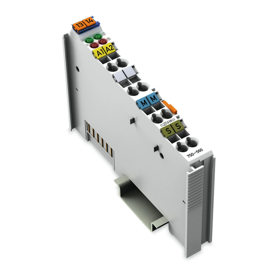
Fig. 2.1.1-1: View g056000e 2.1.1.2 Description The analog output module 750-560 creates a standardized signal of 0-10 V. The module has two short circuit protected output channels and enables, for example, the direct wiring of two 3-conductor actuators to the connections AO 1, AC/DC 24 V and 0 V or AO 2, AC/DC 24 V and 0 V. -
Page 12: Display Elements
However, if such a case should occur, another supply module must be added. The analog output module 750-560 can be used with all couplers/controllers of the WAGO-I/O-SYSTEM 750 (except for the economy types 750-320, - 323, -324 and -327). -
Page 13: Schematic Diagram
750-560 [2 AO 0-10V DC 10Bit 10mA 24V] • 13 Schematic Diagram 2.1.1.4 Schematic Diagram Logic AO 1 AO 2 270 pF Error Function 24 V 24 V 10 nF 10 nF Shield Shield (screen) (screen) 750-560 Fig. 2.1.1-3: Schematic Diagram... -
Page 14: Technical Data
14 • 750-560 [2 AO 0-10V DC 10Bit 10mA 24V] Technical Data 2.1.1.5 Technical Data Module Specific Data Number of outputs Voltage supply via Power Jumper Contacts DC 24 V (-15 % ... +20 %) AC 24 V (-15 % ... +10 %), 50 Hz ( -5 % ... +5 %) - Page 15 Permissible operation temperature: 0 °C ≤ T ≤ +60 °C More Information Detailed references to the approvals are listed in the document "Overview Approvals WAGO-I/O-SYSTEM 750", which You can find on the CD ROM ELECTRONICC Tools and Docs (Item-No.: 0888-0412-0001-0101) or in the Internet under: http://www.wago.com ...
-
Page 16: Process Image
750-560 [2 AO 0-10V DC 10Bit 10mA 24V] Process Image 2.1.1.6 Process Image The analog output module 750-560 transmits 16-bit data and 8 status bits per channel. The digitalized output value is transmitted in a data word (16 bits) as output byte 0 (low) and output byte 1 (high) via the process image of the coupler / controller. -
Page 17: Use In Hazardous Environments
• 17 9BAnalog Output Modules 3 Use in Hazardous Environments The WAGO-I/O-SYSTEM 750 (electrical equipment) is designed for use in Zone 2 hazardous areas. The following sections include both the general identification of components (devices) and the installation regulations to be observed. The individual subsections of the "Installation Regulations"... -
Page 18: Marking Configuration Examples
Approval body and/or number of the examination IECEx PTB 07.0064X certificate I M2 / II 3 GD Explosion protection group and Unit category Ex nA Type of ignition and extended identification Explosion protection group Temperature class WAGO-I/O-SYSTEM 750 I/O Modules... - Page 19 Figure 3: Side marking example for Ex i and IEC Ex i approved I/O modules according to CENELEC and IEC Figure 4: Text detail – Marking example for Ex i and IEC Ex i approved I/O modules according to CENELEC and IEC WAGO-I/O-SYSTEM 750 I/O Modules...
- Page 20 Device category: Zone 2 device (Zone 0 subunit) Explosion protection mark Type of protection: Non-sparking operating equipment [ia] Category of type of protection intrinsic safety: Even safe when two errors occur Explosion Group Temperature class: Max. surface temperature 135°C WAGO-I/O-SYSTEM 750 I/O Modules...
-
Page 21: Marking For America According To Nec 500
Table 3: Description of marking example for I/O modules according to NEC 500 Printing on Text Description CL 1 Explosion protection group (condition of use category) DIV 2 Area of application (zone) Grp. ABCD Explosion group (gas group) Optemp code T4 Temperature class WAGO-I/O-SYSTEM 750 I/O Modules... -
Page 22: Installation Regulations
NFPA 70 National Electrical Code Art. 500 Hazardous Locations ANSI/ISA-RP 12.6-1987 Recommended Practice C22.1 Canadian Electrical Code Notice the following points When using the WAGO-I/O SYSTEM 750 (electrical operation) with Ex approval, the following points are mandatory: WAGO-I/O-SYSTEM 750 I/O Modules... -
Page 23: Special Conditions For Safe Operation Of The Atex And Iec Ex (Acc. Demko 08 Atex 142851X And Iecex Ptb 07.0064)
3.2.1 Special Conditions for Safe Operation of the ATEX and IEC Ex (acc. DEMKO 08 ATEX 142851X and IECEx PTB 07.0064) The fieldbus-independent I/O modules of the WAGO-I/O-SYSTEM 750-.../...-... must be installed in an environment with degree of pollution 2 or better. In the final... -
Page 24: Special Conditions For Safe Use (Atex Certificate Tüv 07 Atex 554086 X)
554086 X) For use as Gc- or Dc-apparatus (in zone 2 or 22) the field bus independent I/O modules WAGO-I/O-SYSTEM 750-*** shall be erected in an enclosure that fulfils the requirements of the applicable standards (see the marking) EN 60079-0, EN 60079-11, EN 60079-15, EN 61241-0 and EN 61241-1. For use as... - Page 25 If the module is energized do not remove or replace the fuse. Do not separate when energized! Do not separate the module when energized! Separate only in a non-hazardous area! Separate the module only in a non-hazardous area! WAGO-I/O-SYSTEM 750 I/O Modules...
-
Page 26: Special Conditions For Safe Use (Iec-Ex Certificate Tun 09.0001
3.2.3 Special conditions for safe use (IEC-Ex Certificate TUN 09.0001 For use as Dc- or Gc-apparatus (in zone 2 or 22) the fieldbus independent I/O modules WAGO-I/O-SYSTEM 750-*** shall be erected in an enclosure that fulfils the requirements of the applicable standards (see the marking) IEC 60079-0, IEC 60079-11, IEC 60079-15, IEC 61241-0 and IEC 61241-1. - Page 27 If the module is energized do not remove or replace the fuse. Do not separate when energized! Do not separate the module when energized! Separate only in a non-hazardous area! Separate the module only in a non-hazardous area! WAGO-I/O-SYSTEM 750 I/O Modules...
-
Page 28: Ansi/Isa 12.12.01
Devices containing fuses must not be fitted into circuits subject to over loads! Devices containing fuses must not be fitted into circuits subject to over loads, e.g. motor circuits! WAGO-I/O-SYSTEM 750 I/O Modules... - Page 29 Proof of certification is available on request. Also take note of the information given on the module technical information sheet. The Instruction Manual, containing these special conditions for safe use, must be readily available to the user. WAGO-I/O-SYSTEM 750 I/O Modules...
- Page 30 WAGO Kontakttechnik GmbH & Co. KG Postfach 2880 • D-32385 Minden Hansastraße 27 • D-32423 Minden Phone: 05 71/8 87 – 0 Fax: 05 71/8 87 – 1 69 E-Mail: info@wago.com Internet: http://www.wago.com...
Need help?
Do you have a question about the 750-560 and is the answer not in the manual?
Questions and answers