Table of Contents
Advertisement
Quick Links
Introduction
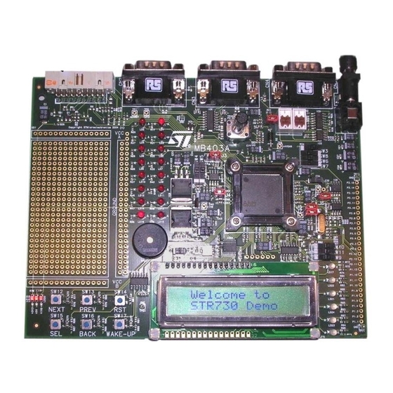
The STR730-EVAL board is a complete development platform for the STR73x series.
It is a cost effective, flexible and open design to demonstrate the capability of the STR730
series of flash micro-controllers and to enable rapid evaluation of the STR73x devices and
available peripherals.
It includes the high performance STR730F ARM7TDMITM processor running at up to
36 MHz, that features a rich set of peripherals and serial communication interfaces,
including CAN (controller area network), STR730F, SPI EEPROM, I2C EEPROM and an
LCD display.
The board can be used as a versatile stand-alone test platform, supporting a CAN interface
and a UART RS232 interface, LED displays, 2 x 16 LCDs, piezo buzzer, test buttons, a JTAG
connector and an analog channel.
A wide choice of third party development tools are readily available in addition to the those
available from STMicroelectronics.
Figure 1.
June 2008
STR730-EVAL evaluation board for STR73xF
STR730-EVAL board
Host to JTAG
interface
High speed JTAG
debug port
connection
STR730-EVAL board
Rev 1
UM0559
User Manual
www.st.com
1/29
Advertisement
Table of Contents

Subscribe to Our Youtube Channel
Related Manuals for ST STR730-EVAL


Summary of Contents for ST STR730-EVAL
- Page 1 STR730-EVAL evaluation board for STR73xF Introduction The STR730-EVAL board is a complete development platform for the STR73x series. It is a cost effective, flexible and open design to demonstrate the capability of the STR730 series of flash micro-controllers and to enable rapid evaluation of the STR73x devices and available peripherals.
-
Page 2: Table Of Contents
Contents UM0559 Contents Introduction ..........3 Processor and memory devices on this board . -
Page 3: Introduction
The STR730-EVAL board is based on the STR730FZ2T7, a highly integrated microcontroller, running at up to 36 MHz that uses the popular ARM7TDMI... -
Page 4: Board Interface Connections
Introduction UM0559 Board interface connections Diagrams and wiring descriptions for these connectors are provided in Chapter 4: Schematics on page 19. The following connections are supported by the board: CAN uses a single 9 D-type connector with microswitch selectable low or high speed transceiver: CN4 UART0 (Rx and Tx only) connected to a 9-way male D-type RS232 connector: CN2 UART1 (Rx and Tx only) connected to a 9-way male D-type RS232 connector: CN3... -
Page 5: Hardware
UM0559 Hardware Hardware Figure 2. STR730-EVAL board layout block diagram LD 2 LD 1 RS232-A RS232-B LD 4 LD 3 UART 0 UART 1 L9616 IC5 LD 6 LD 5 Rx and Tx only Rx and Tx only LD 8... - Page 6 Hardware UM0559 Figure 3. STR730-EVAL board system block diagram Prototype area LEDs GPIO4/PWM High speed/ CAN0/ fault tolerant In-circuit JTAG CAN1 CANH and emulator CANL GPIO RS232 UART0 Rx and Tx I2C0 EEPROM RS232 Rx and Tx UART1 BSPI2 EEPROM...
-
Page 7: Overview
UM0559 Hardware Overview The STR730-EVAL board is a general purpose evaluation platform with CAN (controller area network), and RS232 interfaces. Processor The board supports the STR730FZ2T7 ARM7TDMITM silicon - 144-pin TQFP version. This chip runs at a frequency of up to 36 MHz. -
Page 8: Rs232 Serial Interfaces
Hardware UM0559 RS232 serial interfaces Two general purpose, asynchronous serial I/O data ports are connected through 9-pin D- type male connectors refer to Section 3.2: RS232 serial data connector on page RS232-A connects directly to UART0, transmit and receive only. RS232-B connects to UART1, transmit and receive only. -
Page 9: Push Buttons
UM0559 Hardware Table 1. Software controlled LEDs (continued) Connected to Color Schematic LD17 PWM5_P2.7 Red/green LD21 PWM3_P2.5 LD22 PWM4_P2.6 Figure 10 on page 19 LD23 PWM1_P2.3 LD24 PWM2_P2.4 LD25 PWM0_P2.0 2.10.2 Status LED LD19 is the +5 V power indicator. This LED is red, see Figure 11 on page 2.11 Push buttons... -
Page 10: Option Jumper Placement
Hardware UM0559 2.12 Option jumper placement Figure 4. Option jumpers and switches STR730FZ2T7 ARM7TDMITM Prototype area PREV BACK WAKE-UP SW12 SW13 SW14 SW15 SW16 SW17 SW10 SW11 10/29... -
Page 11: Option Switch Settings
UM0559 Hardware Table 3. Option jumpers Jumper Schematic Description Default Figure 17 on page 26 CAN link: not fitted / fitted (default) Fitted Figure 11 on page 20 CPUIO: +5 V Fitted Figure 10 on page 19 XTAL2 Fitted Figure 10 on page 19 TST pull-down FItted Figure 10 on page 19... - Page 12 Hardware UM0559 Table 4. Option switch settings (continued) Switch Schematic Description Default CAN device select: channel 0 / channel 1 Note SW6 and SW8 must be changed together. Figure 10 on page 19 1-2 = channel 0 2-3 = channel 1 Bit Boot M0, boot from internal flash, see Table Figure 10 on page 19...
- Page 13 UM0559 Hardware Table 5. Boot modes BootM1 BootM0 Memory Mode Note mapping SW11 STR730 Flash sector B0F0 All flash sectors visible except User1 mapped at 0h system memory sector SW10 BOOT M1 SW11 BOOT M0 STR730 Flash sector B0F0 Flash B0F1 sector and system User2 mapped at 0h memory sector not visible...
-
Page 14: Connectors
Connectors UM0559 Connectors CAN bus connector Figure 7. CAN connector 9 pin male D-type: CN4 CAN - data Table 6. CAN connector pinout: CN4 Description Pin Description Pin Description Not connected Not connected 7 CAN H, high side bus output CAN L, low side bus output 5 Not connected 8 Pull down to ground... -
Page 15: Debug
In order for hardware and JTAG RESET to be synchronized, (R3, R6, R5,C2,TR2, TR1) have to be fitted, see Figure 16: ARM JTAG interface on page Input/output summary Table 9. STR730-EVAL board input/output summary Port Peripheral Alternate function Interrupt P0.0... - Page 16 Connectors UM0559 Table 9. STR730-EVAL board input/output summary (continued) Port Peripheral Alternate function Interrupt P0.13 TP54 ICAPB3 P0.14 TP55 OCMPB3 P0.15 TP56 OCMPA3 P1.0 TP57 OCMPA4 P1.1 Test Point OCMPB4 P1.2 Test Point ICAPB4 P1.3 Test Point ICAPA4 P1.4 Test Point P1.5...
- Page 17 UM0559 Connectors Table 9. STR730-EVAL board input/output summary (continued) Port Peripheral Alternate function Interrupt P3.0 10K_POT AIN0 P3.1 LM35_THERM AIN1 P3.2 Test Point AIN2 P3.3 Test Point AIN3 P3.4 Test Point AIN4 P3.5 Test Point AIN5 P3.6 Test Point AIN6 P3.7...
- Page 18 Connectors UM0559 Table 9. STR730-EVAL board input/output summary (continued) Port Peripheral Alternate function Interrupt P5.3 M95_EE_CS OCMPB9 P5.4 CPU_IO nSS2 P5.5 M95_EE_CLK SCLK2 WUP23 P5.6 M95_EE_MOSI MOSI2 P5.7 M95_EE_MISO MISO2 P5.8 SW_NEXT INT6 P5.9 SW_PREV INT7 P5.10 SW_SEL INT8 P5.11...
-
Page 19: Schematics
UM0559 Schematics Schematics Figure 10. STR730-EVAL board top sheet 1 of 2 19/29... - Page 20 Schematics UM0559 Figure 11. STR730-EVAL board top sheet 2 of 2 20/29...
- Page 21 UM0559 Schematics Figure 12. RS232 interface 21/29...
- Page 22 Schematics UM0559 Figure 13. SPI EEPROM interface 22/29...
- Page 23 UM0559 Schematics Figure 14. GPIO LCD 23/29...
- Page 24 Schematics UM0559 Figure 15. LED interface 24/29...
- Page 25 UM0559 Schematics Figure 16. ARM JTAG interface 25/29...
- Page 26 Schematics UM0559 Figure 17. CAN interface 26/29...
- Page 27 UM0559 Schematics Figure 18. I2C EEPROM interface 27/29...
-
Page 28: Revision History
Revision history UM0559 Revision history Table 10. Document revision history Date Revision Changes 26-Jun-2008 Initial release. 28/29... - Page 29 No license, express or implied, by estoppel or otherwise, to any intellectual property rights is granted under this document. If any part of this document refers to any third party products or services it shall not be deemed a license grant by ST for the use of such third party products or services, or any intellectual property contained therein or considered as a warranty covering the use in any manner whatsoever of such third party products or services or any intellectual property contained therein.
Need help?
Do you have a question about the STR730-EVAL and is the answer not in the manual?
Questions and answers