Table of Contents
Advertisement
Introduction
The ST-LINK/V2 is an in-circuit debugger/programmer for the STM8 and STM32
microcontrollers. The single wire interface module (SWIM) and the JTAG/serial wire
debugging (SWD) interfaces facilitate communication with any STM8 or STM32
microcontroller operating on an application board.
In addition to providing the same functionalities of the ST-LINK/V2, the ST-LINK/V2-ISOL
features digital isolation between the PC and the target application board. It also withstands
voltages of up to 1000 V
The USB full-speed interface enables communication with a PC and:
•
STM8 devices via ST Visual Develop (STVD) or ST Visual Program (STVP) software
(available from STMicroelectronics)
•
STM32 devices via IAR
STM32CubeMonitor integrated development environments.
April 2024
ST-LINK/V2 in-circuit debugger/programmer
.
RMS
™
®
, Keil
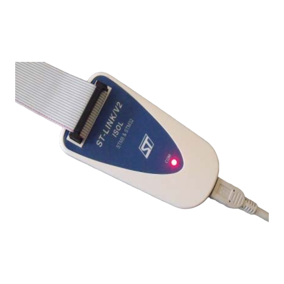
Figure 1. ST-LINK/V2 and ST-LINK/V2-ISOL
ST-LINK/V2
UM1075 Rev 10
, STM32CubeIDE, STM32CubeProgrammer, and
UM1075
User manual
for STM8 and STM32
ST-LINK/V2-ISOL
1/20
www.st.com
1
Advertisement
Table of Contents

Related Manuals for ST ST-LINK/V2


Summary of Contents for ST ST-LINK/V2
-
Page 1: Figure 1. St-Link/V2 And St-Link/V2-Isol
(SWD) interfaces facilitate communication with any STM8 or STM32 microcontroller operating on an application board. In addition to providing the same functionalities of the ST-LINK/V2, the ST-LINK/V2-ISOL features digital isolation between the PC and the target application board. It also withstands... -
Page 2: Table Of Contents
ST-LINK/V2 status LED ........ - Page 3 SWIM flat ribbon connections for ST-LINK/V2 ........
- Page 4 SWIM ST-LINK/V2 standard ERNI cable ........
-
Page 5: Features
ST-LINK/V2-ISOL In-circuit debugger/programmer with digital isolation a. The ST-LINK/V2 can communicate with targets operating below 3.3 V but generates output signals at this voltage level. STM32 targets are tolerant to this overvoltage. If some other components of the target board are sensible, use ST-LINK/V2-ISOL, STLINK-V3MINIE, or STLINK-V3SET with a B-STLINK-VOLT adapter to avoid the impact of overvoltage injection on the board. -
Page 6: Product Contents
Figure 3. They include (from left to right): • USB standard-A to Mini-B cable (A) • ST-LINK/V2 debugging and programming (B) • SWIM low-cost connector (C) • SWIM flat ribbon with a standard ERNI connector at one end (D) •... -
Page 7: Figure 3. St-Link/V2-Isol Product Contents
UM1075 Product contents Figure 3. ST-LINK/V2-ISOL product contents UM1075 Rev 10 7/20... -
Page 8: Hardware Configuration
The ST-LINK/V2-ISOL provides one connector for the STM8 SWIM, STM32 JTAG/SWD, and SWV interfaces. Figure 4. ST-LINK/V2 (on the left) and ST-LINK/V2-ISOL (on the right) connectors 1. A = STM32 JTAG and SWD target connector 2. B = STM8 SWIM target connector 3. -
Page 9: Connection With Stm8
4.1.1 Standard ERNI connection with SWIM flat ribbon Figure 5 shows how to connect the ST-LINK/V2 if a standard ERNI 4-pin SWIM connector is present on the application board. Figure 5. ERNI connector 1. A = Target application board with ERNI connector 2. -
Page 10: Low-Cost Swim Connection
4.1.2 Low-cost SWIM connection Figure 7 shows how to connect the ST-LINK/V2 if a 4-pin, 2.54 mm, low-cost SWIM connector is present on the application board. Figure 7. Low-cost connection 1. A = Target application board with 4-pin, 2.54 mm, low-cost connector 2. -
Page 11: Table 2. Swim Flat Ribbon Connections For St-Link/V2
GROUND RESET RESET MCU RESET pin 1. The power supply from the application board is connected to the ST-LINK/V2 debugging and programming board to ensure signal compatibility between both boards. Figure 8. Target SWIM connector Table 3 summarizes the signal names, functions, and target connection signals using the separate-wires cable. -
Page 12: Connection With Stm32
VDD (3.3 V) Not connected Not connected 1. The power supply from the application board is connected to the ST-LINK/V2 debugging and programming board to ensure signal compatibility between the boards. 2. Connect to GND for noise reduction on the ribbon. -
Page 13: Table 5. Jtag/Swd Cable Connections On Stlink-V2-Isol
Not connected Not connected Not connected 1. The power supply from the application board is connected to the ST-LINK/V2 debugging and programming board to ensure signal compatibility between the boards. 2. Connect to GND for noise reduction on the ribbon. -
Page 14: Figure 9. Jtag And Swd Connection
Hardware configuration UM1075 Figure 9 shows how to connect the ST-LINK/V2 to a target using the JTAG cable. Figure 9. JTAG and SWD connection 1. A = Target application board with JTAG connector 2. B = JTAG/SWD 20-wire flat cable 3. -
Page 15: St-Link/V2 Status Led
TC2050-IDC or TC2050-IDC-NL (No legs) (10-pin cable) TC2050-CLIP retaining clip for use with TC2050-IDC-NL (optional) ST-LINK/V2 status LED The LED labeled COM on top of the ST-LINK/V2 shows the ST-LINK/V2 status (whatever the connection type). In detail: • The LED blinks red: the first USB enumeration with the PC is taking place •... -
Page 16: Software Configuration
The ST-LINK/V2 embeds a firmware upgrade mechanism for in-place upgrades through the USB port. As the firmware can evolve during the life of the ST-LINK/V2 product (new functionality, bug fixes, support for new microcontroller families), it is recommended to visit periodically the dedicated pages on www.st.com... -
Page 17: Schematics
UM1075 Schematics Schematics Figure 11. SWIM ST-LINK/V2 standard ERNI cable Target board (horizontal mount) STLINK/V2 board Note: The connector is located on the edge of the board Cable length 100mm Low cost female connector ST-LINK/V2 02 201 3047 male connector 02... -
Page 18: Figure 12. Swim St-Link/V2 Low-Cost Cable
Schematics UM1075 Figure 12. SWIM ST-LINK/V2 low-cost cable ST-LINK/V 2 b oard Target board Application male Low cost Low cost connector Cable length 100 mm female female 02 20 227 2041 connector connector 02 201 3047 02 201 3047 ST-LINK/V2... -
Page 19: Revision History
Added Note Table Added Note “For low-cost applications...” before Section 3.3: ST- LINK/V2 status LEDs on page 18-Oct-2012 Added Section 5.1: ST-LINK/V2 firmware upgrade on page 25-Mar-2016 Updated V value in Introduction and Features. Updated Table 4: JTAG/SWD cable connections and its footnotes. - Page 20 ST products and/or to this document at any time without notice. Purchasers should obtain the latest relevant information on ST products before placing orders. ST products are sold pursuant to ST’s terms and conditions of sale in place at the time of order acknowledgment.
Need help?
Do you have a question about the ST-LINK/V2 and is the answer not in the manual?
Questions and answers