Table of Contents
Advertisement
Quick Links
Download this manual
See also:
User Manual
Advertisement
Table of Contents

Related Manuals for ST ST7 Series


Summary of Contents for ST ST7 Series
- Page 1 ST7 FAMILY USB LOW-SPEED EVALUATION BOARD GETTING STARTED October 2002 DOC-USB LOW-SPEED Evaluation Board...
- Page 2 USE IN LIFE SUPPORT DEVICES OR SYSTEMS MUST BE EXPRESSLY AUTHORIZED. STMicroelectronics PRODUCTS ARE NOT AUTHORIZED FOR USE AS CRITICAL COMPONENTS IN LIFE SUPPORT DEVICES OR SYSTEMS WITHOUT THE EXPRESS WRITTEN APPROVAL OF STMicroelectronics. As used herein: 1. Life support devices or systems are those 2.
-
Page 3: Introduction
The objective of this evaluation board is to provide you with a complete USB application package using a Windows-based host software application and one of ST’s range of USB low- speed microcontrollers acting as a peripheral device. The host software and the ST7 source code provide an easily-understood example of how to exchange data using the HID class pro- tocols. -
Page 4: Table Of Contents
Table of Contents INTRODUCTION ............1 1 GETTING STARTED . -
Page 5: Getting Started
ST7 USB Low-Speed Evaluation Board 1 GETTING STARTED 1.1 SYSTEM REQUIREMENTS In order to use the USB evaluation board with the Windows operating system, a recent version of Windows, such as Windows 98, Windows Millennium or Windows 2000 must be installed on the PC. -
Page 6: Hardware Installation
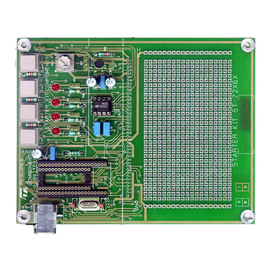
ST7 USB Low-Speed Evaluation Board 1.4 HARDWARE INSTALLATION Figure 1 shows the location of the main components of the evaluation board. The schematic drawing is given in Figure Figure 1. Evaluation Board Layout Jumper W7 Jumper W1 Jumper W6 Trimmer SW4=Reset SDIP32 Socket USB Connector... -
Page 7: Device Selection
ST7 USB Low-Speed Evaluation Board Figure 2. Device selection for A/D conversion W6 JUMPER ST72F62 ST72F63B If you are using the analog trimmer, select the installed ST7 device using jumper W6 as shown Figure 2. This ties the analog trimmer to the PA0 I/O port of the ST72F62 and to the PB0 port of the ST72F63B. -
Page 8: Running The Usb Low Speed Evaluation Board
ST7 USB Low-Speed Evaluation Board 2 RUNNING THE USB LOW SPEED EVALUATION BOARD 2.1 INTRODUCTION The USB Low-Speed Evaluation Board application consists of two main parts: a HID demon- strator running on a PC and the evaluation board itself. Communications between the PC and the ST7 board are done through different USB pipes: –... -
Page 9: Hid Demonstrator
ST7 USB Low-Speed Evaluation Board 2.2 HID DEMONSTRATOR 2.2.1 USB ENUMERATION The Devices selection tabsheet, shown in Figure 4, displays the following information: – Available USB HID devices: All the HID devices connected to the PC are displayed in this window. -
Page 10: Communication With The Evaluation Board
ST7 USB Low-Speed Evaluation Board 2.2.2 COMMUNICATION WITH THE EVALUATION BOARD 2.2.2.1 Controlling the evaluation board from a host PC The HID demonstration tabsheet, shown in Figure 5, displays the following information: Click on the ON/OFF button in the application dialog box to switch ON the LED LD2 on the board. -
Page 11: Adding Circuitry On The Wire-Wrap Area
ST7 USB Low-Speed Evaluation Board 2.4 ADDING CIRCUITRY ON THE WIRE-WRAP AREA The evaluation board features a 43-hole row with all the microcontroller pins plus one side of the analog trimmer. These connection points can be used for signal probing or rewiring to the wire-wrap area. - Page 12 ST7 USB Low-Speed Evaluation Board Figure 6. Board Schematics OSCIN OSCIN OSCOUT OSCOUT RESET RESET VSSA VSSA USBDM USBDM USBDP USBDP USBVCC USBVCC VDDA VDDA W1B1 10/12...
-
Page 13: Proposal For Sdip42/Dip20 Adaptor
ST7 USB Low-Speed Evaluation Board 2.5 PROPOSAL FOR SDIP42/DIP20 ADAPTOR Figure 7. Adaptor Layout 11/12... - Page 14 This publication supersedes and replaces all information previously supplied. STMicroelectronics products are not authorized for use as critical components in life support devices or systems without the express written approval of STMicroelectronics. The ST logo is a registered trademark of STMicroelectronics 2002 STMicroelectronics - All Rights Reserved.
Need help?
Do you have a question about the ST7 Series and is the answer not in the manual?
Questions and answers