Table of Contents
Advertisement
Quick Links
Introduction
The STR910 evaluation board (STR910-EVAL) is a complete development platform for the
STMicroelectronic's ARM
STR91xF includes Pre-fetch Queue and Branch cache, full speed USB 2.0 compatible port,
Ethernet 100/10 interface, Embedded MAC, CAN2.0B compliant interface, a 2 Mbyte dual
bank Flash memory, a 96 Kbyte SRAM and many peripherals.
The STR910-EVAL board includes an STR910F microcontroller, pre-loaded demonstration
software and a full range of hardware features to help you evaluate device peripherals (such
as motor control, IrDA, USB, Ethernet, CAN) and develop your own applications. Extension
headers make it possible to easily connect a daughter board or wrapping board for your
specific application.
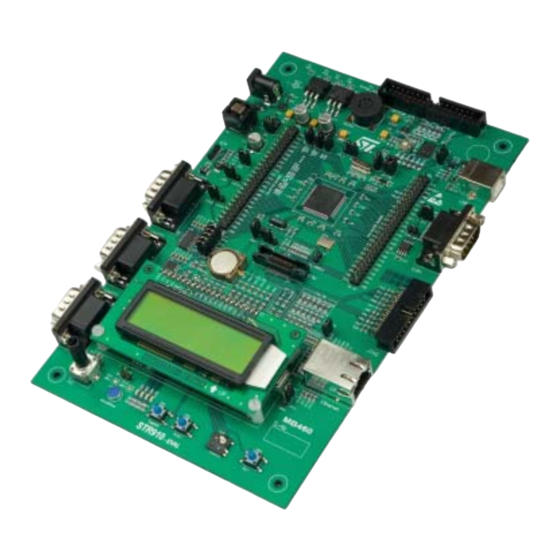
Figure 1.
Features
■
Three 5V power supply options: jack, USB connection or a daughter board
■
RTC with tamper detection
■
Audio play and record
■
Three RS232 connectors with support of full modem control on one connector
■
Infrared Data Access (IrDA)
■
USB 2.0 compliant with full-speed (12 Mb/s) data transmission
■
CAN 2.0B connection
■
Inductor motor control connector with 6 PWM output, emergency stop and tachometer
input
November 2007
®
core-based STR91xF. Based on the ARM966ES core, the
STR910-EVAL evaluation board
Rev 3
UM0174
User manual
STR910-EVAL
evaluation board
www.st.com
1/46
Advertisement
Table of Contents

Related Manuals for ST STR910-EVAL


Summary of Contents for ST STR910-EVAL
-
Page 1: Figure 1. Str910-Eval Evaluation Board
User manual STR910-EVAL evaluation board Introduction The STR910 evaluation board (STR910-EVAL) is a complete development platform for the ® STMicroelectronic’s ARM core-based STR91xF. Based on the ARM966ES core, the STR91xF includes Pre-fetch Queue and Branch cache, full speed USB 2.0 compatible port, Ethernet 100/10 interface, Embedded MAC, CAN2.0B compliant interface, a 2 Mbyte dual... -
Page 2: About The User Manuals
Extension connectors for daughter board or wrapping board About the user manuals... This user manual provides information about using your STR910-EVAL and its hardware features. This product includes the STR912FAW47X6 microcontroller with a 2 Mbyte internal Flash memory. Earlier versions of the product include the STR912FAW44X6 microcontroller with a 512 Kbyte internal Flash memory. -
Page 3: Table Of Contents
UM0174 Contents Contents About the user manuals..........2 Ordering information . - Page 4 Contents UM0174 Schematics ..........30 Appendix A Implemented STR912F pin functions.
- Page 5 UM0174 List of tables List of tables Table 1. Power jumpers ............11 Table 2.
- Page 6 STR910-EVAL evaluation board connectors ........19...
-
Page 7: Getting Started
UM0174 Getting started Getting started Your STR910-EVAL is designed with a full range of hardware features that will help you rapidly evaluate microcontroller peripherals and develop your own applications. Descriptions of hardware features and configurations are provided in Section 2 on page Demonstration software is preloaded in the board’s flash memory for easy demonstration of... -
Page 8: Hardware Layout And Configuration
Figure 3. Hardware block diagram Peripheral implementation on the STR910-EVAL board requires the use of alternate pin functions supported by the STR912FAW47X6. A table of alternate pin functions used in this design is provided in... -
Page 9: Figure 4. Str910-Eval Evaluation Board Layout
UM0174 Hardware layout and configuration Figure 4. STR910-EVAL evaluation board layout Motor control Speaker, U5 Daughter board connector, CN1 extension connectors, CN5, CN6 Power supply jack, CN2 USB type B connector, CN3 STR912, U10 IrDA, U9 CAN D-type 9- pin connector,... -
Page 10: Power Supply
Not fitted Fitted Power supply STR910-EVAL evaluation board is designed to be powered by a 5V DC power supply. It is possible to configure the evaluation board to use any of the following three sources for the power supply: ●... -
Page 11: Clock Source
Enables consumption measurement of STR91xF backup power supply (VBAT). JP15 Default setting: Fitted The LD1 LED is lit when the STR910-EVAL evaluation board is powered correctly. Clock source Four clock sources are available on the STR910-EVAL evaluation board for the microcontroller, USB, RTC and Ethernet PHY transceiver. -
Page 12: Reset Source
To use the internal clock of the STR91xF, JP17 is not fitted. In this case P27 can be used for an alternate function. Default setting: Not fitted Reset source The reset signal of STR910-EVAL evaluation board is low active. The reset sources include: ● Power On Reset from STM1001 (U7) ●... -
Page 13: Audio Features
UM0174 Hardware layout and configuration Audio features STR910-EVAL evaluation board supports both audio recording and playback. This can be disabled or enabled by setting of jumpers JP5 and JP26. Audio volume can be adjusted using the potentiometer RV1. Table 4. -
Page 14: Rs232 And Irda
Default setting: Not fitted RS232 and IrDA Three channels for RS232 communication are available on the STR910-EVAL board. Two channels UART2 and UART3, use the RS232 transceiver U14 and two male D-type 9- pin connectors CN10 and CN12. IrDA communication is supported as a multiplex function on UART2. -
Page 15: Motor Control
Default setting: Fitted Motor control STR910-EVAL board supports induction motor control via a 34-pin connector CN1, which provides all required control and feedback signals to and from a motor power-drive board. Available signals on this connector include emergency stop, motor speed, 3-phase motor current, bus voltage, Heatsink temperature from the motor drive board and 6 channels of PWM control signals going to the motor drive circuit. -
Page 16: Rtc And Tamper
PB1 can be used to simulate a tamper event on the RTC. 2.11 The STR910-EVAL evaluation board offers USB 2.0 compliant communication via a USB type-B connector (CN3) with full-speed (12Mb/s) data transfer. The evaluation board and daughter board can be powered from this USB connection at 5V DC with a 500mA current limitation. -
Page 17: Development And Debugging Tool Support
Hardware layout and configuration 2.12 Development and debugging tool support The STR910-EVAL evaluation board supports connection to both In-Circuit Emulators (ICE) via a 20-pin standard JTAG interface and Trace tools via a 38-pin Embedded Trace Macrocell (ETM) interface. To enable the ETM trace feature, some alternate circuit functions have to be disconnected... -
Page 18: Display And Input Devices
32x122 pixel graphic LCD and 4 general purpose LED's (LD2, 3, 4, 5) are available as display devices. A 4-direction joystick with selection key and one general purpose button (PB3) are available as input devices. STR910-EVAL also supports a second optional 2x16 character LCD that can be mounted on the U17 connector. Table 10. -
Page 19: Connectors
UM0174 Connectors Connectors The following sections provide pin descriptions for the STR910-EVAL evaluation board connectors shown in Figure Figure 6. STR910-EVAL evaluation board connectors CAN type D, 9-pin JTAG debug USB type B male connector CN4 connector CN9 connector CN3... -
Page 20: Motor Control Connector Cn1
Connectors UM0174 Motor control connector CN1 Figure 7. Motor control connector (CN1, top view) 33 31 29 27 25 23 21 19 17 15 13 11 9 7 5 34 32 30 28 26 24 22 20 18 16 14 12 10 8 6 Top view Table 11. -
Page 21: Power Supply Connector Cn2
UM0174 Connectors Power supply connector CN2 Your STR910-EVAL evaluation board can be powered from a DC 5V power supply via the external power supply jack (CN2) shown in Figure 8. The central pin of CN2 must be positive. For power supply jumper configurations, refer to section Section 2.1 on page... -
Page 22: Can Type D, 9-Pin Male Connector Cn4
Connectors UM0174 CAN type D, 9-pin male connector CN4 Figure 10. CAN type D, 9-pin male connector (CN4, front view) Front view Table 13. CAN type D, male 9-pin male connector (CN4) Pin number Description Pin number Description 1, 4, 5 CANH CANL CANV+ (3.3V) -
Page 23: Rs232 With Full Modem Control Cn8
UM0174 Connectors Table 14. ETM trace connector (CN7) (continued) Pin number Description Pin number Description TRACECLK TRST DBGRQ TRACEPKT[3] DBGACK TRACEPKT[2] nSRST TRACEPKT[1] EXTTRIG TRACEPKT[0] Vtref PIPESTAT[2] RTCK PIPESTAT[1] Vsupply PIPESTAT[0] RS232 with full modem control CN8 Figure 12. RS232 connector (CN8, front view) Front view Table 15. -
Page 24: Jtag Debug Connector Cn9
Connectors UM0174 JTAG debug connector CN9 Figure 13. JTAG debug connector (CN9, top view) 19 17 15 13 11 9 7 5 20 18 16 14 12 10 8 6 Top view Table 16. JTAG debug connector (CN9) Pin number Description Pin number Description... -
Page 25: Ethernet Rj45 Connector Cn11
UM0174 Connectors Table 17. RS232 connectors (CN10, CN12) Pin number Description Pin number Description CN10 UART2_RXD UART2_TXD CN12 UART3_RXD UART3_TXD Ethernet RJ45 connector CN11 Figure 15. Ethernet RJ45 connector (CN11, front view) Front view Table 18. Ethernet RJ45 connector (CN11) Pin number Description Pin number... -
Page 26: Daughter Board Extension Connector Cn5 And Cn6
Two 50-pin male headers CN5 and CN6 can be used to connect a daughter board or standard wrapping board to the STR910-EVAL evaluation board. All 80 GPI/Os and the EMI interface control signals are available on these connectors. Each pin on CN5 and CN6 can be used by a daughter board after disconnecting it from the corresponding function block on the STR910-EVAL evaluation board. - Page 27 Remove R52 Ethernet Remove R76 Ethernet Remove R74 Joystick Remove R92 None Disconnect STR910-EVAL evaluation board from Motor control motor power drive board Motor control JP7 is not fitted. Disconnect STR910-EVAL evaluation board from Motor control motor power drive board...
-
Page 28: Table 19. Daughter Board Extension Connector (Cn5)
Ethernet Remove R53 Place JP16 in position 1•2 and remove R105. Motor control TAMPER_IN None RESET# None Ethernet Remove R56 Disconnect STR910-EVAL evaluation board from Motor control motor power drive board SPI Flash Remove R15 D5V(note1) Ethernet Remove R73 EMI_ALE... - Page 29 Disconnect STR910-EVAL evaluation board from ETM Trace ETM trace LED3 Remove R84 LED1 Remove R82 None Note: The D5V pin can be used to power the STR910-EVAL board from the power supply provided by the daughter board. 29/46...
-
Page 30: Schematics
Schematics UM0174 Schematics This section provides design schematics for the STR910-EVALboard key features, which are provided to help you implement these features in your own application designs. Schematics are provided for: ● STR910F microcontroller connections (Figure ● Power supply (Figure ●... -
Page 31: Figure 17. Str910-Eval Microcontroller Connections
UM0174 Schematics Figure 17. STR910-EVAL microcontroller connections 31/46... -
Page 32: Figure 18. Power Supply
Schematics UM0174 Figure 18. Power supply 32/46... -
Page 33: Figure 19. Can And Usb Connections
UM0174 Schematics Figure 19. CAN and USB connections 33/46... -
Page 34: Figure 20. Uart And Irda Connections
Schematics UM0174 Figure 20. UART and IrDA connections 34/46... -
Page 35: Figure 21. Ethernet Connection
UM0174 Schematics Figure 21. Ethernet connection 35/46... -
Page 36: Figure 22. Audio Peripherals
Schematics UM0174 Figure 22. Audio peripherals 36/46... -
Page 37: Figure 23. Jtag, Etm And Daughter Board Connections
UM0174 Schematics Figure 23. JTAG, ETM and daughter board connections 37/46... -
Page 38: Figure 24. Lcd And Joystick
Schematics UM0174 Figure 24. LCD and joystick 38/46... -
Page 39: Appendix A Implemented Str912F Pin Functions
The table indicates the pin functions used for STR910-EVAL peripherals in blue. If you choose to implement the Embedded Trace Module (ETM) connector for your debugging tool, you will use the alternate functions for specific pins that are indicated in gray instead of the function indicated in blue. - Page 40 Implemented STR912F pin functions UM0174 Table 21. Implemented pin functions of the STR912FAW47X6 (continued) Alternate functions Default input Pin # Pin name For peripheral... function Input 1 Output 1 Output 2 Output 3 UART0_CTS I2C0_CLKIN GPIO_2.0 I2C0_CLKOUT ETM_PCK0 P2.0 Clear To Send I2C clock in GP Output I2C clock out...
- Page 41 UM0174 Implemented STR912F pin functions Table 21. Implemented pin functions of the STR912FAW47X6 (continued) Alternate functions Default input Pin # Pin name For peripheral... function Input 1 Output 1 Output 2 Output 3 ADC7 TIM3_CAPB GPIO_4.7 TIM3_COMB ETM_TRSYNC P4.7 Microphone in ADC input chnl Input Capture GP Output...
- Page 42 Implemented STR912F pin functions UM0174 Table 21. Implemented pin functions of the STR912FAW47X6 (continued) Alternate functions Default input Pin # Pin name For peripheral... function Input 1 Output 1 Output 2 Output 3 EXINT28 UART0_RxD GPIO_7.4 8b) EMI_A4 EMI_CS3n Joystick P7.4 External Intr UART rcv data...
-
Page 43: Appendix B Product Support
You can order extra components, such as sockets and adapters, from STMicroelectronics, from the component manufacturer or from a distributor. To help you find what you need, a listing of accessories for ST development tools is available on the STMicroelectronics microcontrollers support site at www.st.com. -
Page 44: Getting Prepared Before You Call
(for example, the UK, Continental Europe or the USA). Serial Number: The serial number is found located on the rear panel of the ST Micro Connect box and is also listed on the Global Reference card provided with the emulator. -
Page 45: Revision History
UM0174 Revision history Revision history Table 22. Document revision history Date Revision Changes 12-Apr-2006 First draft release for review. Added explanation of schematic version numbers (Section Replaced board schematics C.0 with modified schematics C.1. 17-May-2006 Changes to revision C.1 schematics include: R50 on JTAG connector changed to “Do not fit”... - Page 46 No license, express or implied, by estoppel or otherwise, to any intellectual property rights is granted under this document. If any part of this document refers to any third party products or services it shall not be deemed a license grant by ST for the use of such third party products or services, or any intellectual property contained therein or considered as a warranty covering the use in any manner whatsoever of such third party products or services or any intellectual property contained therein.
Need help?
Do you have a question about the STR910-EVAL and is the answer not in the manual?
Questions and answers