Table of Contents
Advertisement
Quick Links
Getting started with STEVAL-A6986IV3 evaluation board based on A6986I,
configured as isobuck-boost and delivering four selectable dual voltages
Introduction
The
STEVAL-A6986IV3
is an evaluation board based on ST A6986I.
The
A6986I
is designed for isolated applications and normally implements an iso-buck architecture.
The
STEVAL-A6986IV3
board adopts an inverting buck-boost topology at the primary side (instead of a standard buck), hence
building an isobuck-boost (so called from now on).
The advantages in using the isobuck-boost instead of a buck are mainly: higher deliverable power at the secondary side,
optimization of the transformer design.
The input voltage is up to 28 V. Since the primary side performs an inverting buck-boost conversion, the primary output voltage
is negative.
The secondary side of the board consists of four independent windings, each one intended to provide the supply for a gate
driver (see block diagram on page 2) thanks to a very accurate post regulation.
The isobuck-boost architecture exploits the power capability of the A6986I, delivering up to 60 mA for three secondary channels
and up to 180 mA for the fourth one.
A microswitch provides the possibility to select two regulated voltage pairs for each channel: 18 V / - 5 V or 15 V / - 8 V. The
regulation of these voltages is achieved by using the LDH40 (for the positive voltage) and a shunt regulator TL431B (for the
negative voltage). The expanded output voltage range (up to 22 V) of the LDH40 makes it ideal for this kind of application.
Thanks to the LDH40 and the TL431B, the described post regulation allows a voltage accuracy well below ±1%.
The availability of four well-regulated dual voltages makes this solution ideal for gate driving in three-phase inverters.
UM3340 - Rev 1 - May 2024
For further information contact your local STMicroelectronics sales office.
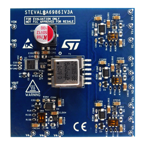
Figure 1.
STEVAL-A6986IV3 board picture
UM3340
User manual
www.st.com
Advertisement
Table of Contents

Related Manuals for ST STEVAL-A6986IV3


Summary of Contents for ST STEVAL-A6986IV3
-
Page 1: Figure 1. Steval-A6986Iv3 Board Picture
UM3340 User manual Getting started with STEVAL-A6986IV3 evaluation board based on A6986I, configured as isobuck-boost and delivering four selectable dual voltages Introduction STEVAL-A6986IV3 is an evaluation board based on ST A6986I. A6986I is designed for isolated applications and normally implements an iso-buck architecture. -
Page 2: Getting Started
The electrical installation shall be completed in accordance with the appropriate requirements (for example, cross-sectional areas of conductors, fusings, and GND connections). Functional block diagram Figure 2. STEVAL-A6986IV3 board block diagram PRIMARY SIDE SECONDARY SIDE Secondary... -
Page 3: How To Use The Board
Set the supply voltage VIN from 4V to 28V and switch the power supply on. Step 4. Vary the loads (if possible) and read the voltages and/or check the relevant signals. Figure 3. STEVAL-A6986IV3 board layout Load 1 Power supply... -
Page 4: Connectors And Test Points
UM3340 Connectors and test points Connectors and test points This connector is for input supply voltage. This voltage is provided, through the input EMI filter, to the pin VIN of the device. A power supply ranging from 4V to 28V should be connected to this test point, setting a proper current limit. -
Page 5: Input Emi Filter
UM3340 Input EMI filter Input EMI filter STEVAL-A6986IV3 embeds an EMI filter (bottom side). The EMI filter consists of: • A double pi filter with an inductor (Lf2) • A ferrite bead (Lf1) • Three MLCC capacitors (Cf1, Cf2, and Cf3) •... -
Page 6: Board Setting Capability
UM3340 Board setting capability Board setting capability STEVAL-A6986IV3 provides the possibility to set two different voltage pairs at the four isolated outputs by using the available four microswitches SWn (with n = 1, 2, 3, 4). Figure 4. Microswitches for isolated output voltage selection The selection of the desired voltages can be done according to the below figure. -
Page 7: Snubber
UM3340 Snubber Snubber In parallel with the Schottky diode of each winding a snubber network (resistor and capacitor in series) is implemented (see figure below). Figure 6. Snubber network in parallel with the Schottky diode The need for the snubber derives from: •... -
Page 8: Steval-A6986Iv3 Emc Compliance
STEVAL-A6986IV3 EMC compliance STEVAL-A6986IV3 is certified by an external supervisor company and Class B compliant with the following standards. Table 1. List of standards which the STEVAL-A6986IV3 complies with Reference standard Standard application EN IEC 61000-6-1:2019 Full EN IEC 61000-6-3:2021... -
Page 9: Figure 9. Radiated Emc Test Results Of The Steval-A6986Iv3
UM3340 STEVAL-A6986IV3 EMC compliance Figure 9. Radiated EMC test results of the STEVAL-A6986IV3 Note: The graph is extracted from the report REP029174_EMC_61000 issued by NEMKO SpA. UM3340 - Rev 1 page 9/25... -
Page 10: Steval-A6986Iv3 Performance
UM3340 STEVAL-A6986IV3 performance STEVAL-A6986IV3 performance The following graphs show the load regulation performances of the isolated output voltages downstream of the postregulation networks. The cumulative isolated output current indicated on the x-axis is the sum of the current drawn from all the outputs. -
Page 11: Figure 16. Load Regulation Of The Isolated Outputs Vs Current From Each Output. Vin = 12V Option 15V/-8V
UM3340 STEVAL-A6986IV3 performance Figure 16. Load regulation of the isolated outputs Figure 17. Load regulation of the isolated outputs vs current from each output. V = 12V option vs current from each output. V = 12V option 15V/-8V 15V/-8V The postregulation helps achieving excellent accuracy of the regulated voltages and is essential to split the isolated voltages of each secondary winding into the desired voltage values. -
Page 12: Thermal Performance
The temperature of the top side of the package for the A6986I is around 50°C, for the LDH40 is instead around 70°C for the one with 180mA, around 45°C for the ones with 60mA. Figure 20. STEVAL-A6986IV3 thermal picture = 12V, I = 60mA, I = 180mA, T = 25°C... -
Page 13: Other Voltage Settings
Other voltage settings According to the final application, different isolated voltages might be required. The voltage pairs provided by the STEVAL-A6986IV3 are mainly suitable for driving SiC and IGBT. Nevertheless, with minor and easy changes, the same board can be used to generate other common voltages. -
Page 14: Option 12V (Single)
UM3340 Other voltage settings 10.2 Option 12V (single) The single voltage 12V can be generated with the following changes: • Rfb1 = 5.5kΩ, instead of 11kΩ (reducing the primary output voltage) • R1, R5, R9,R13 = 7.5kΩ instead of 11.5kΩ (setting 12VV for the positive isolated voltage) •... -
Page 15: Schematic Diagrams
UM3340 Schematic diagrams Schematic diagrams Figure 28. STEVAL-A6986IV3 circuit schematic (1 of 2) Rsn1 Csn1 Vout_iso1 Bottom Ciso1 GND_iso1 Cgnd1 Rsn2 Csn2 GND1 GND_iso1 Cgnd2 Vout_iso2 GND1 GND_iso2 Ciso2 GND_iso2 Cgnd3 GND_iso3 GND1 Rsn3 Cgnd4 Csn3 GND_iso4 GND1 Vout_iso3 Ciso3... -
Page 16: Bill Of Materials
UM3340 Bill of materials Bill of materials Table 2. STEVAL-A6986IV3 bill of materials Item Q.ty Ref. Part / Value Description Manufacturer Order code CGA3E3X7R1H474K080A CVcc 470nF MLCC CGA3E2C0G1H4R7C080A 4.7pF MLCC CAP CER 680PF 50V 680pF MLCC Samsung C0G/NP0 0603 MLCC Cf1,Cf2,Cf3 4.7uF... - Page 17 UM3340 Bill of materials Item Q.ty Ref. Part / Value Description Manufacturer Order code 56kΩ SMD resistor Panasonic ERJ-UP3F5602V Rfb1 11kΩ SMD resistor Panasonic ERJ-UP3F1102V Rfb2 1kΩ SMD resistor ROHM ESR03EZPF1001 Rsn1,Rsn2,R 1kΩ SMD resistor Vishay CRCW08051K00FKEAHP sn3,Rsn4 R1, R5, R9, 11.5kΩ...
-
Page 18: Main Parameters Of The Transformer Zc1905-Be
UM3340 Main parameters of the transformer ZC1905-BE Main parameters of the transformer ZC1905-BE Table 3. Main parameters of the transformer ZC1905-BE Description Value Turn ratio 1:2.7 Magnetizing inductance 20µH Leakage inductance 250nH Primary winding resistance 50mΩ Secondary winding resistance (HS1) 1.95Ω... -
Page 19: Board Versions
UM3340 Board versions Board versions Table 4. STEVAL-A6986IV3 versions Finished good Schematic diagrams Bill of materials STEVAL$A6986IV3A STEVAL$A6986IV3A schematic diagrams STEVAL$A6986IV3A bill of materials 1. This code identifies the STEVAL-A6986IV3 evaluation board first version. UM3340 - Rev 1 page 19/25... -
Page 20: Regulatory Compliance Information
UM3340 Regulatory compliance information Regulatory compliance information Notice for US Federal Communication Commission (FCC) For evaluation only; not FCC approved for resale FCC NOTICE - This kit is designed to allow: (1) Product developers to evaluate electronic components, circuitry, or software associated with the kit to determine whether to incorporate such items in a finished product and (2) Software developers to write software applications for use with the end product. -
Page 21: Revision History
UM3340 Revision history Table 5. Document revision history Date Revision Changes 07-May-2024 Initial release. UM3340 - Rev 1 page 21/25... -
Page 22: Table Of Contents
STEVAL-A6986IV3 EMC compliance........ -
Page 23: List Of Tables
List of standards which the STEVAL-A6986IV3 complies with ....... . . -
Page 24: List Of Figures
Radiated EMC test results of the STEVAL-A6986IV3 ........ - Page 25 ST’s terms and conditions of sale in place at the time of order acknowledgment. Purchasers are solely responsible for the choice, selection, and use of ST products and ST assumes no liability for application assistance or the design of purchasers’...
Need help?
Do you have a question about the STEVAL-A6986IV3 and is the answer not in the manual?
Questions and answers