Table of Contents
Advertisement
Quick Links
WCP SS Swerve - User Guide
(Rev 1)
What is the WCP SS Swerve? ����������������������������������������������������������������������������3
1� Design Notes ��������������������������������������������������������������������������������������������������4
1�1 Tools Needed ���������������������������������������������������������������������������������������5
1�2 BOM (Bill of Materials) ������������������������������������������������������������������������6
1�3 Encoders ����������������������������������������������������������������������������������������������8
2� Left and Right Module Setup �������������������������������������������������������������������������9
3� Assembly of Base Kit ���������������������������������������������������������������������������������� 10
3�1 Top Rotation Bearing Retaining Bolts ��������������������������������������������� 11
3�2 Insert Rotation Bearing �������������������������������������������������������������������� 12
3�3 Bottom Rotation Bearing Retaining Bolts ��������������������������������������� 13
3�4 Main Rotation Gear and Rotation Bearing �������������������������������������� 14
3�5 Insert Bearing into Wheel Fork �������������������������������������������������������� 15
3�6 Insert Roll Pins into Wheel Fork ������������������������������������������������������ 16
3�7 1
Stage Shaft Assembly ����������������������������������������������������������������� 17
3�8 Install Wheel Forks ��������������������������������������������������������������������������� 18
3�10 Insert Base Plate Rotation Bearings ��������������������������������������������� 20
3�11 CIM Output Shaft ���������������������������������������������������������������������������� 21
3�12 1
Stage Rotation Shaft ����������������������������������������������������������������� 22
3�13 2
Stage Shaft Install �������������������������������������������������������������������� 23
3�14 2
Stage Shaft Final Gear Assembly ��������������������������������������������� 24
3�15 1
Stage Rotation Shaft Final Gear Install ������������������������������������ 25
3�16 Secure Motor Plate ������������������������������������������������������������������������ 26
3�17 1
Stage Rotation Shaft Motor Plate Bearing ������������������������������ 27
WCP SS Swerve - User Manual (Rev 1)
Table of Contents
Stage Shaft ������������������������������������������������� 19
Page 1
Advertisement
Table of Contents

Related Manuals for WCP SS Swerve

Summary of Contents for WCP SS Swerve
-
Page 1: Table Of Contents
Stage Shaft Final Gear Assembly ��������������������������������������������� 24 3�15 1 Stage Rotation Shaft Final Gear Install ������������������������������������ 25 3�16 Secure Motor Plate ������������������������������������������������������������������������ 26 3�17 1 Stage Rotation Shaft Motor Plate Bearing ������������������������������ 27 WCP SS Swerve - User Manual (Rev 1) Page 1... - Page 2 3�27 Installing the Dead Axle Pt� 2 �������������������������������������������������������� 37 3�28 Installing Completed Wheel into Module �������������������������������������� 38 3�29 Securing Wheel To Module ������������������������������������������������������������ 39 3�30 Base WCP SS Swerve Module Complete �������������������������������������� 40 4� Installing Distance Sensor Hardware Kit ��������������������������������������������������� 41 4�1 Main Distance Sensor Bearing �������������������������������������������������������� 42 4�2 Distance Encoder Shaft and Pulley �������������������������������������������������...
-
Page 3: What Is The Wcp Ss Swerve
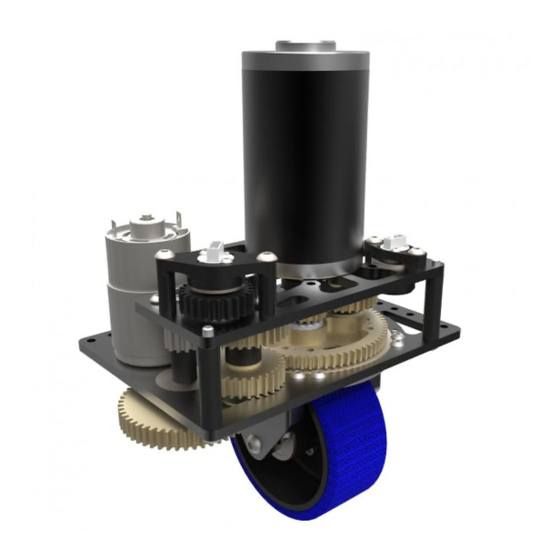
(Rev 1) What is the WCP SS Swerve? The WCP SS Swerve is the most robust and ease of use COTS swerve module available on the market� Through its precision-engineered main rotation gear and easy to change drive wheel, it makes it easy to service the module and make changes very quickly�... -
Page 4: 1� Design Notes
The following pages will explain tools needed to assemble the gearbox and other vari- ous tidbits of information� Disclaimer: Teams are responsible for purchasing or making the hex shaft spacers shown as they are not included in the kit WCP SS Swerve - User Manual (Rev 1) Page 4... -
Page 5: 1�1 Tools Needed
WCP SS Swerve - User Guide (Rev 1) 1.1 Tools Needed To assemble the WCP SS Swerve, it is recommended teams use: 1� Allen Wrenches 1� 1/8” (McMaster P/N: 37095A22) 2� 5/32” (Mcmaster Carr P/N: 5419A35) 2� 7/16” Ratcheting Combination Wrench (McMaster P/N: 5163A15) 1�... -
Page 6: 1�2 Bom (Bill Of Materials)
- 1 x 15T Bevel Gear - 1 x 45T Bevel Gear - 1 x 72T Rotation Gear - 2 x Forks - 1 x Dead Axle Wheel Shaft - 1 x 4” Aluminum Wheel WCP SS Swerve - User Manual (Rev 1) Page 6... - Page 7 - 1 x 8mm Snapring - 1 x 3�25” BHCS 1/4”-20 Bolt - 1 x 3/8” BHCS #10-32 Bolt - 1 x 1�75” SHCS #10-32 BOlt - 1 x 1/4-20” Thin Lock Nut WCP SS Swerve - User Manual (Rev 1) Page 7...
-
Page 8: 1�3 Encoders
The WCP SS Swerve only natively supports the SRX Mag Encoder by CTRE� Note: Distance and Rotation hardware are sold separately� It is highly recommended to purchase these hardware kits as they are designed around the WCP SS Swerve mod- ule�... -
Page 9: 2� Left And Right Module Setup
The assembly instructions are the same for each side of the module in terms of the steps, but in order to get the left or right side modules you must start with the base plate face up or face down� WCP SS Swerve - User Manual (Rev 1) Page 9... -
Page 10: 3� Assembly Of Base Kit
WCP SS Swerve - User Guide (Rev 1) 3. Assembly of Base Kit WCP SS Swerve - User Manual (Rev 1) Page 10... -
Page 11: 3�1 Top Rotation Bearing Retaining Bolts
WCP SS Swerve - User Guide (Rev 1) 3.1 Top Rotation Bearing Retaining Bolts Insert 14 of the #10-32 BHCS Bolt x 0�25” Length into the threaded holes shown� Tight- en all the bolts down� WCP SS Swerve - User Manual (Rev 1) Page 11... -
Page 12: 3�2 Insert Rotation Bearing
Insert main large circular cutout as shown� This should require a little force as it is a snug fit for the bearing. If necessary tap lightly and evenly with a deadblow. WCP SS Swerve - User Manual (Rev 1) Page 12... -
Page 13: 3�3 Bottom Rotation Bearing Retaining Bolts
Insert 9 of the #10-32 BHCS x 0�375” Length bolts into the threaded holes as shown below� Note: Bolts will not be able to thread all the way into the plate as the bearing will stop this from happening WCP SS Swerve - User Manual (Rev 1) Page 13... -
Page 14: 3�4 Main Rotation Gear And Rotation Bearing
Push the main rotation gear onto the large rotation bearing as shown below� Ensure that you are putting the gear on the side of the bearing where the bolts are flush with the plate� WCP SS Swerve - User Manual (Rev 1) Page 14... -
Page 15: 3�5 Insert Bearing Into Wheel Fork
WCP SS Swerve - User Guide (Rev 1) 3.5 Insert Bearing into Wheel Fork Push bearing into the small circular cutout as shown below� Ensure that the bearing is seated properly� WCP SS Swerve - User Manual (Rev 1) Page 15... -
Page 16: 3�6 Insert Roll Pins Into Wheel Fork
WCP SS Swerve - User Guide (Rev 1) 3.6 Insert Roll Pins into Wheel Fork Push the 4 roll pins into the smaller set of holes on both forks� WCP SS Swerve - User Manual (Rev 1) Page 16... -
Page 17: St Stage Shaft Assembly
Note: It may be easier to insert the 2mm machine key into the grove on the shaft then slide the 15T bevel gear over the machine key and shaft� WCP SS Swerve - User Manual (Rev 1) Page 17... -
Page 18: 3�8 Install Wheel Forks
Note: The roll pins are there to aid in assembly and alignment. If difficult to push roll pins into holes you can drill out the 0�125” holes to the next size up and this will not affect performance� SHCS WCP SS Swerve - User Manual (Rev 1) Page 18... -
Page 19: 3�9 Finish Assembly Of 1 St Stage Shaft
3.9 Finish Assembly of 1 Stage Shaft Assemble 30T or your chosen driven gear for the distance set of gears and put 1/2” snap ring onto shaft to retain the gear� WCP SS Swerve - User Manual (Rev 1) Page 19... -
Page 20: 3�10 Insert Base Plate Rotation Bearings
Insert bearings as shown and thread in the bolts into the plate so that they retain the bearing� Note: These bolts will not sit flush with the plate as they are meant to only retain the bearing� WCP SS Swerve - User Manual (Rev 1) Page 20... -
Page 21: 3�11 Cim Output Shaft
Disclaimer: If you are using a CIM or Mini CIM as the distance motor you will not be able to get how far you have driven unless you use a Falcon 500 or another method to track distance. WCP SS Swerve - User Manual (Rev 1) Page 21... -
Page 22: St Stage Rotation Shaft
1st stage rotation gear, in our case we chose the 50T 1/2” hex bore gear for example� Retain the gear and wave washer via the 1/2” snap ring� WCP SS Swerve - User Manual (Rev 1) Page 22... -
Page 23: Nd Stage Shaft Install
Slide 2nd stage shaft into the bearing installed in 3�10 then slide the 30T 1/2” hex bore gear onto the shaft such that it mates with the main rotation gear� WCP SS Swerve - User Manual (Rev 1) Page 23... -
Page 24: St Stage Shaft Final Gear Assembly
WCP SS Swerve - User Guide (Rev 1) 3.14 2 Stage Shaft Final Gear Assembly Slide a 1/2” spacer onto the shaft followed by the 34T 1/2” hex bore gear� WCP SS Swerve - User Manual (Rev 1) Page 24... -
Page 25: St Stage Rotation Shaft Final Gear Install
Note: Some may find it easier to push the 2mm machine key into the grove then slide the 12T CIM bore gear onto the shaft after the key is installed� WCP SS Swerve - User Manual (Rev 1) Page 25... -
Page 26: 3�16 Secure Motor Plate
Push the 4 x #10-32 BHCS x 2�0” length from the holes in the base plate and then slip module spacers over the bolts and finally thread the bolts into the holes located on the motor plate as shown below� WCP SS Swerve - User Manual (Rev 1) Page 26... -
Page 27: St Stage Rotation Shaft Motor Plate Bearing
2 x #10-32 BHCS x 0�25” Length bolts� Note: These bolts will not sit flush with the plate as they are meant to only retain the bearing� WCP SS Swerve - User Manual (Rev 1) Page 27... -
Page 28: St Stage Rotation Shaft
Note: The shaft may not fully show the snap ring grove and this is normal� Please push on the bottom of the shaft so that the wave washer compresses and then the snap ring grove will be fully present� WCP SS Swerve - User Manual (Rev 1) Page 28... -
Page 29: Nd Stage Rotation Shaft Motor Plate Bearing
2 x #10-32 BHCS x 0�25” length bolts� Note: These bolts will not sit flush with the plate as they are meant to only retain the WCP SS Swerve - User Manual (Rev 1) Page 29... -
Page 30: 3�20 Align Drive Motor Onto Motor Plate
Note: If you are using our distance hardware or have 3D printed your own then it is recommended that the GT2 belt is slipped over the pulley prior to the drive motor being installed as it is difficult to install when the motor is mounted. WCP SS Swerve - User Manual (Rev 1) Page 30... -
Page 31: 3�21 Mounting The Drive Motor
Note: If you need to replace your drive motor for any reason you will have to remove the drive wheel to access these bolts in the future� WCP SS Swerve - User Manual (Rev 1) Page 31... -
Page 32: 3�22 775Pro Mounting
After the pinion of choice is installed on the 775pro, slide the motor into it’s location as shown below and secure the motor to the base plate with 2 x M4 bolts x 12mm length� Note: These M4 bolts are not included WCP SS Swerve - User Manual (Rev 1) Page 32... -
Page 33: 3�23 Secureing 45T Bevel Gear To Wheel
Then secure the bevel gear to the wheel by tightening the 5 x #10- 32 SHCS bolts x 0�375” length from the back side of the wheel so that none of the bolt heads are visible when looking at the 45T bevel gear� WCP SS Swerve - User Manual (Rev 1) Page 33... -
Page 34: 3�24 Install Bevel Gear Bearing
Push the 0�5” ID x 1�125” OD x 0�313” WD Flanged Bearing into the bevel gear so that the flange of the bearing is flush with the outside lip on the bevel gear. WCP SS Swerve - User Manual (Rev 1) Page 34... -
Page 35: 3�25 Install Backside Wheel Bearing
3.25 Install Backside Wheel Bearing Push the 0�5” ID x 1�125” OD x 0�313” WD Flanged Bearing into the extruded feature on the rear of the wheel as shown below� WCP SS Swerve - User Manual (Rev 1) Page 35... -
Page 36: 3�26 Installing The Dead Axle Pt� 1
(Rev 1) 3.26 Installing the Dead Axle Pt. 1 Slide the dead axle wheel shaft into the bearing from the bevel gear side and secure with the 1/2” snap ring� WCP SS Swerve - User Manual (Rev 1) Page 36... -
Page 37: 3�27 Installing The Dead Axle Pt� 2
Secure the shaft to the wheel by installing the 1/2” snap ring on to the end of the shaft� The dead axle should not be able to separte from the wheel once this snap ring is intalled� WCP SS Swerve - User Manual (Rev 1) Page 37... -
Page 38: 3�28 Installing Completed Wheel Into Module
WCP SS Swerve - User Guide (Rev 1) 3.28 Installing Completed Wheel into Module Slide the completed wheel into the the forks so that the cutouts on the forks surround the dead axle wheel shaft� WCP SS Swerve - User Manual (Rev 1) Page 38... -
Page 39: 3�29 Securing Wheel To Module
Note: This bolt can be installed with the bolt head is touching the fork shown below or the opposite fork� Installing this bolt the opposite way will not effect performance� WCP SS Swerve - User Manual (Rev 1) Page 39... -
Page 40: 3�30 Base Wcp Ss Swerve Module Complete
WCP SS Swerve - User Guide (Rev 1) 3.30 Base WCP SS Swerve Module Complete WCP SS Swerve - User Manual (Rev 1) Page 40... -
Page 41: 4� Installing Distance Sensor Hardware Kit
WCP SS Swerve - User Guide (Rev 1) 4. Installing Distance Sensor Hardware Kit WCP SS Swerve - User Manual (Rev 1) Page 41... -
Page 42: 4�1 Main Distance Sensor Bearing
WCP SS Swerve - User Guide (Rev 1) 4.1 Main Distance Sensor Bearing Push the 0�375” ID x 0�875” OD x 0�28” WD bearing into the motor plate as shown be- low� WCP SS Swerve - User Manual (Rev 1) Page 42... -
Page 43: 4�2 Distance Encoder Shaft And Pulley
The shaft is not geared 1:1 with the drive wheel so the shaft will be rotating faster than the wheel rotations� If the distance encoder shaft is not spinning then it has been installed incorrectly� WCP SS Swerve - User Manual (Rev 1) Page 43... -
Page 44: 4�3 Ctre Mag Encoder Mount
Disclaimer: Do not over tighten the 2x #10-32 BHCS bolts x 0.5” length into the plate as over tightening them can cause the 3D printed part to be deformed. WCP SS Swerve - User Manual (Rev 1) Page 44... -
Page 45: 4�4 Distance Sensor Hardware Kit Complete
WCP SS Swerve - User Guide (Rev 1) 4.4 Distance Sensor Hardware Kit Complete WCP SS Swerve - User Manual (Rev 1) Page 45... -
Page 46: 5� Installing Rotation Sensor Hardware Kit
WCP SS Swerve - User Guide (Rev 1) 5. Installing Rotation Sensor Hardware Kit WCP SS Swerve - User Manual (Rev 1) Page 46... -
Page 47: 5�1 Main Rotation Sensor Bearing
WCP SS Swerve - User Guide (Rev 1) 5.1 Main Rotation Sensor Bearing Push the 0�25 ID x 0�625” OD x 0�196” WD bearing into the hole shown below� WCP SS Swerve - User Manual (Rev 1) Page 47... -
Page 48: 5�2 10T 3D Printed Rotation Pinion
Disclaimer: If the 10T 3D printed rotatin pinion is damaged due to excessive force it will not be replaced by WestCoast Products. WCP SS Swerve - User Manual (Rev 1) Page 48... -
Page 49: 5�3 24T 3D Printed Rotation Gear
5.3 24T 3D Printed Rotation Gear Install the rotation encoder shaft by putting the smaller end into the previously installed bearing and then slip the 24T 3D printed rotation gear onto the shaft� WCP SS Swerve - User Manual (Rev 1) Page 49... -
Page 50: 5�4 3D Printed Ctre Mag Encoder Mount
Disclaimer: Do not over tighten the 2x #10-32 BHCS bolts x 1.25” length into the plate as over tightening them can cause the 3D printed part to be deformed. WCP SS Swerve - User Manual (Rev 1) Page 50... -
Page 51: 5�5 Rotation Sensor Hardware Kit Complete
WCP SS Swerve - User Guide (Rev 1) 5.5 Rotation Sensor Hardware Kit Complete WCP SS Swerve - User Manual (Rev 1) Page 51...
Need help?
Do you have a question about the SS Swerve and is the answer not in the manual?
Questions and answers