
Subscribe to Our Youtube Channel
Related Manuals for Altera Cyclone III FPGA


Summary of Contents for Altera Cyclone III FPGA
- Page 1 Cyclone III FPGA Starter Board Reference Manual 101 Innovation Drive San Jose, CA 95134 www.altera.com Document Date: October 2007...
- Page 2 Altera Corporation in the U.S. and other countries. All other product or service names are the property of their respective holders. Al- tera products are protected under numerous U.S.
-
Page 3: Table Of Contents
Parallel Flash ........................... 2–16 DDR SDRAM ..........................2–18 SSRAM ............................. 2–19 Power Supply ............................2–22 Statement of China-RoHS Compliance .................... 2–23 Additional Information Revision History ..........................Info–i How to Contact Altera ........................Info–i Typographic Conventions ......................Info–ii Altera Corporation October 2007 Preliminary... - Page 4 Contents Stratix Device Handbook, Volume 1 Altera Corporation Preliminary October 2007...
-
Page 5: Chapter 1. Introduction
General This reference manual provides comprehensive information about the ® ® Altera Cyclone III family of devices and the Cyclone III FPGA starter Description board. ® The Cyclone III starter board provides a hardware platform that offers a unique opportunity to customize your development environment via expansion connectors and daughter cards as well as evaluate the feature- ®... -
Page 6: Board Component Blocks
For external configuration of Cyclone III device ● ® ® For system debugging using the SignalTap and Nios ● debugging console Communications port for Board Diagnostic graphical user ● interface (GUI) 1–2 Reference Manual Altera Corporation Cyclone III FPGA Starter Board October 2007... -
Page 7: Block Diagram
Introduction Block Diagram Figure 1–1 shows a functional block diagram of the Cyclone III FPGA starter board. Figure 1–1. Cyclone III FPGA Starter Board HSMC Switches Parallel Flash 16MB Cyclone III EP3C25F324 LEDs SSRAM Blaster 32MB Handling the When handling the board, it is important to observe the following... - Page 8 Handling the Board 1–4 Reference Manual Altera Corporation Cyclone III FPGA Starter Board October 2007...
-
Page 9: Chapter 2. Board Components & Interfaces
Cyclone III FPGA Starter Kit in the following directory: altera\<version#>\kits\cycloneIII_3c25_start\board_design_files For information on powering-up the Cyclone III FPGA starter board and installing the demo software, refer to the Cyclone III FPGA Starter Kit Getting Started User Guide. Altera Corporation Reference Manual 2–1... - Page 10 Board Overview Figure 2–1 shows the top view of the Cyclone III FPGA starter board. Figure 2–1. Top View of the Cyclone III FPGA Starter Board FPGA Core Power 2.5 V I/O Power Measurement (JP6) Measurement (JP3) 1-Mbyte SSRAM (U5)
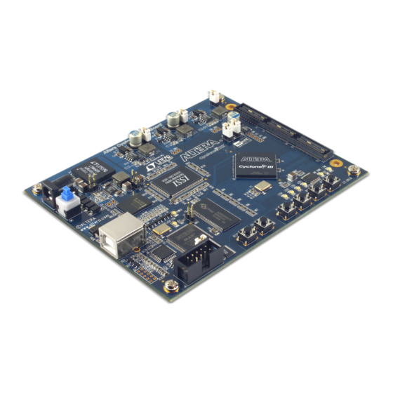
- Page 11 Board Components & Interfaces Figure 2–2 shows the diagonal view of the Cyclone III FPGA starter board. Figure 2–2. Diagonal View of the Cyclone III FPGA Starter Board Altera Corporation Reference Manual 2–3 October 2007 Cyclone III FPGA Starter Board...
- Page 12 Board Overview Table 2–1 describes the components and lists their corresponding board references. Table 2–1. Cyclone III FPGA Starter Board (Part 1 of 2) Component/ Type Board Reference Description Page Interface Featured Device FPGA Cyclone III EP3C25F324-C8, 324-pin FineLine BGA 2–5...
-
Page 13: Featured Device
Current sense Measure 2.5 V I/O power (shared between resistor devices) using current sense resistor. Featured The Cyclone III FPGA Starter Kit features the EP3C25F324 device (U1) in a 324-pin FineLine BGA (FBGA) package. Table 2–2 lists Cyclone III Device device features. -
Page 14: Clocking Circuitry
For additional information about Altera devices, go to www.altera.com/products/devices. Clocking The Cyclone III FPGA starter board’s clocking circuitry is designed to be simple and easy to use. A single 50-MHz clock input is used and all other Circuitry clocks are generated using the Cyclone III device’s phase-locked loops (PLLs). -
Page 15: Jumpers
Figure 2–3 shows the simplest clocking scheme with a single clock input; however, much more complex clocking schemes can be implemented with Cyclone III FPGAs. Figure 2–3. Cyclone III FPGA Starter Board’s Clocking Scheme 16 MB Parallel Flash SSRAM Cyclone III... -
Page 16: Interfaces
USB-Blaster circuitry must be used to configure the Cyclone III device. (The board ships without the JTAG header populated.) Interfaces This section describes the following Cyclone III FPGA starter board’s interface blocks: ■ USB interface ■... -
Page 17: Hsmc Expansion Connector
Table 2–6 lists the ordering codes and shows the relationship between the standard Samtec Q-series connectors and the modified parts’ ordering codes. Table 2–6. Altera-Specific & Standard Samtec Part Numbers Altera-Specific Samtec Standard Samtec Part Part Number Number... -
Page 18: General User Interfaces
.006 REF Table 2–9 lists the HSMC Port A interface pins. Signal names and directions are relative to the Cyclone III FPGA. (The HSMC is operating as the host.) General User Interfaces To allow you to fully leverage the I/O capabilities of the Cyclone III... - Page 19 Bidirectional 2.5 V HSMC_D11 Bidirectional 2.5 V HSMC_D12 Bidirectional 2.5 V HSMC_D13 Bidirectional 2.5 V HSMC_D14 Bidirectional 2.5 V HSMC_D15 Bidirectional 2.5 V HSMC_D16 Bidirectional 2.5 V HSMC_D17 Altera Corporation Reference Manual 2–11 October 2007 Cyclone III FPGA Starter Board...
- Page 20 Bidirectional 2.5 V HSMC_RX_p10 Bidirectional 2.5 V HSMC_TX_n10 Bidirectional 2.5 V HSMC_RX_n10 Bidirectional 2.5 V HSMC_TX_p11 Bidirectional 2.5 V HSMC_RX_p11 Bidirectional 2.5 V HSMC_TX_n11 Bidirectional 2.5 V HSMC_RX_n11 2–12 Reference Manual Altera Corporation Cyclone III FPGA Starter Board October 2007...
-
Page 21: Push Buttons
Direction Type Input 2.5 V KEY0 Input 2.5 V KEY1 Input 2.5 V KEY2 Input 2.5 V KEY3 Input 2.5 V CPU_RESET_N H5 (nConfig) Input 2.5 V RECONFIGURE Altera Corporation Reference Manual 2–13 October 2007 Cyclone III FPGA Starter Board... -
Page 22: Leds
Table 2–11. Board LED Pinout (Part 1 of 2) Signal Name FPGA Pin Name Direction Type Output 2.5 V LED0 Output 2.5 V LED1 Output 2.5 V LED2 Output 2.5 V LED3 Power LED 2–14 Reference Manual Altera Corporation Cyclone III FPGA Starter Board October 2007... - Page 23 Flash signal LED: The flash_CE_n LED illuminates when the CE_n signal to the flash is asserted indicating the flash is being accessed. ■ Power LED: The power LED illuminates when power is applied to the board. Altera Corporation Reference Manual 2–15 October 2007 Cyclone III FPGA Starter Board...
-
Page 24: Memory
Memory Memory The Cyclone III FPGA starter board includes the following memories: ■ Parallel flash ■ DDR SDRAM ■ SSRAM Parallel Flash The Cyclone III starter board has an 8M x 16 low voltage parallel flash. Table 2–12 lists the parallel flash board reference and manufacturing information. - Page 25 2.5 V flash_we_n Output 2.5 V flash_ce_n Output 2.5 V flash_oe_n Output 2.5 V flash_reset_n Output 2.5 V flash_adv_n Output 2.5 V flash_clk (dclk) Output 2.5 V flash_wait Altera Corporation Reference Manual 2–17 October 2007 Cyclone III FPGA Starter Board...
-
Page 26: Ddr Sdram
Memory DDR SDRAM The Cyclone III FPGA starter board has a 4M x 16 x 4 DDR SDRAM. Table 2–14 lists DDR SDRAM board reference and manufacturing information. Table 2–14. DDR SDRAM Manufacturing Information Board Reference Description Manufacturer Manufacturer Part Number... -
Page 27: Ssram
Bidirectional SSTL-2 ddr_dq14 Bidirectional SSTL-2 ddr_dq15 SSRAM The Cyclone III FPGA starter board has a 256K x 32 synchronous SRAM. Table 2–16 lists SSRAM board reference and manufacturing information. Table 2–16. SSRAM Manufacturing Information Board Reference Description Manufacturer Manufacturer Part Number... - Page 28 Bidirectional 2.5 V flash_sram_dq4 Bidirectional 2.5 V flash_sram_dq5 Bidirectional 2.5 V flash_sram_dq6 Bidirectional 2.5 V flash_sram_dq7 Bidirectional 2.5 V flash_sram_dq8 Bidirectional 2.5 V flash_sram_dq9 Bidirectional 2.5 V flash_sram_dq10 2–20 Reference Manual Altera Corporation Cyclone III FPGA Starter Board October 2007...
- Page 29 Output 2.5 V sram_we_n Output 2.5 V sram_be_n0 Output 2.5 V sram_be_n1 Output 2.5 V sram_be_n2 Output 2.5 V sram_be_n3 Output 2.5 V sram_adsc_n Output 2.5 V sram_clk Altera Corporation Reference Manual 2–21 October 2007 Cyclone III FPGA Starter Board...
-
Page 30: Power Supply
You can measure the core and I/O voltage with a current meter while the Cyclone III device is in standby mode. For more information on this circuit, refer to the Cyclone III FPGA Starter Kit Getting Started User Guide. 2–22... - Page 31 X* indicates that the concentration of the hazardous substance of at least one of all homogeneous materials in the parts is above the relevant threshold of the SJ/T11363-2006 standard, but it is exempted by EU RoHS. Altera Corporation Reference Manual 2–23 October 2007 Cyclone III FPGA Starter Board...
-
Page 32: Statement Of China-Rohs Compliance
Statement of China-RoHS Compliance 2–24 Reference Manual Altera Corporation Cyclone III FPGA Starter Board October 2007... -
Page 33: Additional Information
Product literature Website www.altera.com/literature Altera literature services Email literature@altera.com Non-technical support (General) Email nacomp@altera.com Email authorization@altera.com (Software Licensing) Note to table: You can also contact your local Altera sales office or sales representative. Altera Corporation Info-i October 2007 Preliminary... -
Page 34: Typographic Conventions
How to Contact Altera Cyclone FPGA Device Handbook Typographic This document uses the typographic conventions shown below. Conventions Visual Cue Meaning Bold Type with Initial Command names, dialog box titles, checkbox options, and dialog box options are Capital Letters shown in bold, initial capital letters. Example: Save As dialog box.
Need help?
Do you have a question about the Cyclone III FPGA and is the answer not in the manual?
Questions and answers