Advertisement
Quick Links
ELC Distributed I/O Adapters
4
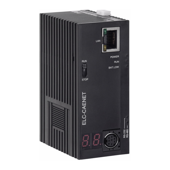
ELC-CAENET
To ensure correct installation and operation of ELC-CAENET, please read this chapter carefully
before using your ELC-CAENET. The ELC-CAENET is an Ethernet remote I/O adapter product
that connects ELC I/O modules to Ethernet networks using either EtherNet/IP or Modbus TCP
protocols. To configure the ELC-CAENET module use EATON's ELCSoft and ECISoft or an
embedded web page on the device.
The ELC-CAENET supports Modbus TCP server protocol and can be used as remote I/O from
a PLC or other Modbus TCP client devices. The ELC-CAENET can also be used as a Modbus
TCP gateway, supporting the conversion from Modbus TCP commands to Modbus ASCII/RTU.
The ELC-ENET also supports EtherNet/IP adapter functionality to provide remote I/O for a PLC
capable of being an EtherNet/IP scanner.
Features
4.1
Supports EtherNet/IP Adapter communication with up to 8 connections.
Supports Modbus TCP server communications with up to 16 connections.
10/100 Mbps transmission speed; MDI/MDI-X auto-detect.
Supports up to 16 expansion modules, including up to 8 analog modules
Supports a maximum of 256 digital Input and Output points.
Integrated Modbus TCP to Modbus serial gateway (Allows a Modbus TCP client to
connect to 32 devices on a local modbus serial link).
Supports embedded "local logic functions": IF-THEN, counter, timer and real-time clock.
Able to operate independently without control from a main PLC.
Real time clock synchronized via NTP
Configurable using embedded web page or Eaton ELCSoft/ECISoft.
Specifications
4.2
Ethernet interface
Interface
Transmission method
Transmission cable
Transmission speed
Communication
protocol
Serial communication interface (COM1)
Interface
Transmission method
Communication speed
Communication format
70
RJ-45 with Auto MDI/MDIX
802.3, 802.3u
Category 5e, 100m (Max)
10/100 Mbps Auto-Detection
ICMP, IP, TCP, UDP, DHCP, SMTP, NTP, MODBUS TCP,
ETHERNET/IP
Mini Din
RS-232
19,200 bps
Stop bit: 1; Parity bit: None; Data bit: 8
For More Information visit: www.eaton.com
MN05002003E
Advertisement

Related Manuals for Eaton ELC-CAENET


Summary of Contents for Eaton ELC-CAENET
- Page 1 The ELC-CAENET supports Modbus TCP server protocol and can be used as remote I/O from a PLC or other Modbus TCP client devices. The ELC-CAENET can also be used as a Modbus TCP gateway, supporting the conversion from Modbus TCP commands to Modbus ASCII/RTU.
- Page 2 Fc)/IEC61131-2 & IEC 68-2-27 (TEST Ea) Certificates Electrical specification 24VDC (-15% ~ 20%) (with DC input polarity reverse Power supply voltage protection) Power fuse capacity 1.85A/30VDC, Polyswitch Power consumption Insulation voltage 500VDC Weight 116g MN05002003E For More Information visit: www.eaton.com...
- Page 3 16. DIN rail (35mm) 6. RS-485 indicator 17. Extension module fixing clip 7. LINK/ACK indicator 18. DIN rail clip 8. SPEED indicator 19. Power supply port 9. Digital display 20. 3P terminal block (standard accessory) For More Information visit: www.eaton.com MN05002003E...
- Page 4 STOP STOP 2. Analog input/output modules are in STOP status. 3. Local logic function halted. 1. ELC-CAENET re-detects the modules on the I/O bus. STOP 2. Analog input/output modules switch from STOP to RUN status. 4.3.5 Ethernet RJ-45 PIN Definition...
- Page 5 Negative pole for data Positive pole for data Installation & Wiring In this section, we will describe how to connect the ELC-CAENET module to other devices and the network. 4.4.1 Connecting the ELC-CAENET to ELC I/O Modules Open the extension clips on the top and bottom of the ELC-CAENET. Connect the extension port of the ELC-CAENET and the I/O module.
- Page 6 Connect ELC-CAENET to the Ethernet switch using CAT-5e twisted pair cable. Since the ELC-CAENET has Auto MDI/MDIX functionality, a cross over cable is not requried to connect directly to a PC. See below for the connection between the PC and ELC-CAENET modules: ELC-COENETM...
- Page 7 ID of the 5th analog I/O module module ID of the 6th analog I/O ID of the 6th analog I/O module module ID of the 7th analog I/O ID of the 7th analog I/O module module For More Information visit: www.eaton.com MN05002003E...
- Page 8 Model code of ELC-CAENET = H’0600. BR# 1: F irmw are Ve rs ion The firmware version of ELC-CAENET is displayed in hex, e.g. H’0100 indicates version V1.00 BR# 2: Re le ase D ate o f th e Vers ion The date in decimal form 10,000s digit and 1,000s digit are for “month”;...
- Page 9 Modbus ASCII Master BR#6: Address For assigning or reading the Modbus serial address of the ELC-CAENET. The address will be displayed in the message display after being set up. Range: 1 ~ 247. BR#7: Number of Digita l Input Points Read the number of digital input points from BR#7.
- Page 10 Extension module error number of I/O points exceeds the maximum and whether the there are more than 8 analog/specialty I/O modules connected. 1. Check if ELC-CAENET and RS-485 are properly Slave error connected. 2. Check if the RS-485 transmission speed is...
- Page 11 Real-time clock (RTC) set-up. When BR#9 = 1, ELC-CAENET will stop to update the RTC values to BR#10 ~ #16. Once the setup is completed, ELC-CAENET will set BR#9 to 0. Allowed range for RTC: 1970/01/01 00:00:00 ~ 2037/12/31 23:59:59...
- Page 12 R C R # 0 ~ #3 99: C ont ro l R eg i ster f o r R ig ht - S id e A na lo g I /O Mod u le s By reading/writing RCR in ELC-CAENET, you are able to store or retrieve the data in the control register (CR) inside the analog input/output module.
- Page 13 C# 1 ~ #1 5: Co un ter 1 ~ 1 5 Same as C#0. 4.5.8 Bit Devices for Real-Time Clock (R) The ELC-CAENET provides a set of 16 flags to be defined based on the internal Real Time Clock. Attribute...
- Page 14 R# 1 ~ #1 5: RTC 1 ~ 15 Same as R#0. Modbus TCP Communications The ELC-CAENET module supports the MODBUS TCP protocol. It acts as a MODBUS TCP server, providing access to the internal data elements described earlier in this document. 4.6.1...
- Page 15 0x3000~0x3190 412289~412689 EtherNet/IP Communications The ELC-CAENET module supports the EtherNet/IP protocol. It acts as an adapter device. It provides access to internal data elements through both implicit I/O connections to the I/O assemblies, and explicit messages to data objects. 4.7.1...
- Page 16 Revision of the item the Revision Identity Object represents Major USINT Revision Minor USINT Revision Status WORD Summary status of device Serial UDINT Serial number of device Number SHORT_ Product Human readable identification “ELC-CAENET” Name STRING MN05002003E For More Information visit: www.eaton.com...
- Page 17 Discrete Discrete Discrete Discrete Discrete Discrete Discrete Discrete #101 Output#24 Output#23 Output#22 Output#21 Output#20 Output#19 Output#18 Output#17 … Discrete Discrete Discrete Discrete Discrete Discrete Discrete Discrete Output#25 Output#25 Output#25 Output#25 Output#25 Output#25 Output#25 Output#24 For More Information visit: www.eaton.com MN05002003E...
- Page 18 Low Byte of CR Read Mapping#2 High Byte of CR Read Mapping#2 Low Byte of CR Read Mapping#3 High Byte of CR Read Mapping#3 … Low Byte of CR Read Mapping#64 High Byte of CR Read Mapping#64 MN05002003E For More Information visit: www.eaton.com...
- Page 19 Default Rule #1 ~ #64 Value WORD BR register Get/Set 4.7.8 RCR Object (0x65) Instance Access Attribute ID Name Data Type Description of Attribute Default Rule #1 ~ Value WORD RCR register Get/Set #400 For More Information visit: www.eaton.com MN05002003E...
- Page 20 Eaton provides software that simplifies the configuration of the ELC-CAENET including the local logic functions. This section gives instructions on how to set up ELC-CAENET using this software and explanation on each setup page. The software uses UDP port 20006 in the set up of the ELC-CAENET.
- Page 21 ELC Distributed I/O Adapters this section. This provides a convenient alternative when the Eaton software is not available. The Web page can be accessed by entering the IP address of the ELC-CAENET into your browser. 4.8.1 Setting up Communications & Searching for Communication Modules with...
- Page 22 Recording IP Address The IP list allows the user to select modules directly and designate a module for search. Recording IP address means to add this ELC-CAENET to the list, allowing the user to see ELC-CAENET in the search. MN05002003E...
- Page 23 In the list, you will see the network IPs already used. Click “Add” to record the known IP address into the list and next search for the module on the network by designated IP. Click the icon to search for the module. For More Information visit: www.eaton.com MN05002003E...
- Page 24 ELC Distributed I/O Adapters 4.8.3 Basic Settings The basic settings include parameters such module name, network settings and communication time. The basic tab MN05002003E For More Information visit: www.eaton.com...
- Page 25 ELC Distributed I/O Adapters Module name: There can be many ELC-CAENET modules on the network. You can set up a module name for each module to identify the module when you need to use them. Network setup: Enable dynamic IP (DHCP) or static IP..
- Page 26 Select the time zone you are in and adjust the offset between the time of your city and Coordinated Universal Time (UTC). 5. Clock setup Set up the time in ELC-CAENET. You can set the time to the same as the PC in operation, or you can set up the time manually. MN05002003E...
- Page 27 IP Filter The IP filter is used for restricting the computers or devices that can establish connection to the ELC-CAENET. Only the IP set within a certain range can establish a connection. Other IPs will be rejected. Setting up IP filter Enable IP filter: Check the box to enable IP filter.
- Page 28 All the settings above can be added to the IF-THEN table below, or you can modify, clear or delete the settings. Up, Down You can move the IF-THEN setting up or down to change the execution order. MN05002003E For More Information visit: www.eaton.com...
- Page 29 The counter can be triggered by the external input points RX. When RX turns from OFF to ON, the counter will start to count. There are 16 counters in the ELC-CAENET, selectable for counting up and counting down. The counting range is -32,768 ~ 32,767.
- Page 30 The real-time clock (RTC) can be triggered by the system at a specific time. There are 16 RTC triggers in ELC-CAENET. You can designate the trigger time or trigger the RTC on a monthly, weekly or daily basis. Please refer to the descriptions for RS#0 ~ RS#159.
- Page 31 Hour, Minute and Second need to be set. If you would like the RTC to be triggered on a weekly basis, you only need to set up Week, Hour, Minute and Second. If the RTC is triggered monthly, set up only Day, Hour, Minute and Second. For More Information visit: www.eaton.com MN05002003E...
- Page 32 ELC-CAENET offers control registers (CR) for analog I/O modules. And has built-in mapping tables for the CR numbers. The user can select the CRs to be read/written and use EATON’s communication module ELC-COENETM to map the CR directly to D registers in ELC-PV controller and utilize these D registers in the program, controlling and monitoring the analog I/O modules connected to ELC-CAENET.
- Page 33 4.8.11 I/O Monitoring Table ELC-CAENET is able to monitor internal registers on-line. Scroll the table to monitor bit devices RX, RY, T, C, R, RCR and BR and the bit status and present value in the register. You can choose to monitor decimal or hex values.
- Page 34 ELC Distributed I/O Adapters Device Select an internal register in the ELC-CAENET. Bit devices: RX, RY, T, C, R Registers: T, C, R, RCR, BR. Number Select the bit devices and registers to be monitored by their numbers. RX#0 ~ RX#255, total 256 bits.
- Page 35 Gateway functions help you quikly store and retrieve data and offers on-line monitoring for maximum of 100 bits of data and words of data. The data can be temporarily stored in the ELC-CAENET, speeding up the write/read and response time.
- Page 36 Enter the number of consecutive words to be monitored (Max. 100). Once the information of slave monitoring is set, click "Apply" to save the setting and start the monitoring. Incomplete device information will be deleted. MN05002003E For More Information visit: www.eaton.com...
- Page 37 The default is in cache enabled mode. You can set up maximum 16 sets of slave information for the monitored bits and words (Max. 100 data). Under the cache mode, you are able to send the read data back to the registers in ELC-CAENET. 4.8.13 Setting up virtual Com The virtual COM converts the data sent to the RS-232 port into Ethernet.
- Page 38 Open the setup page for Virtual COM. Press “Search”, and you will see all the connected devices on the network Select the device and click “OK”. Information on the device will be loaded in automatically. MN05002003E For More Information visit: www.eaton.com...
- Page 39 Once the setup is completed, you will then be able to see the virtual COM just set in “Computer Management”. 4.8.14 Security Setting To prevent the values set in the ELC-CAENET from being modified, you can set up passwords For More Information visit: www.eaton.com MN05002003E...
- Page 40 Once the password is set, none of the configuration pages can be accessed unless you enter the password. However, if you access the ELC-CAENET via RS-232, you can return the module to defaults whether the password isset or not. For example, if...
- Page 41 Check “Factory Setting” box and click on “Yes”. Note: If you set up the ELC-CAENET via RS-232, you can return the settings to defaults whether the password is locked or not. It will take approximately 10 seconds to return to default settings, so DO NOT switch off the power within the until it’s complete.
- Page 42 AI/AO Open Internet Explorer and enter IP address “192.168.1.5” (default) of ELC-CAENET. You can also copy the IP address of ELC-CAENET in ECISoft and paste it to the address column in IE. Press “Enter” on keyboard to open the webpage.
- Page 43 ELC Distributed I/O Adapters In IE, select “Tool” => “Internet Options…”. For More Information visit: www.eaton.com MN05002003E...
- Page 44 ELC Distributed I/O Adapters Select “Connections” and Click “LAN Settings…". Uncheck “Proxy server” options and click "OK”. MN05002003E For More Information visit: www.eaton.com...
- Page 45 ELC Distributed I/O Adapters Set up exceptions: 1. Click “Advanced…” on Local Area Network (LAN) Settings page. 2. Enter the IP address “192.168.1.5” of ELC-CAENET in Exceptions. 3. Click “OK”. Abnormal webpage action: In this case, please clear your temporary Internet files.
- Page 46 2. Check “Delete all offline content” and click "OK” to start the deletion. 3. Click “OK” to leave the “General” page. 4.8.17 Reading the ELC-CAENET EDS file to view/edit analog data When using the web pages to configure and view the data on the Analog I/O Module tab, click the “Read EDS File”...
- Page 47 This application example will demonstrate how to set up an ELC-COENETM Ethernet module to read and write I/O data from an ELC-CAENET Ethernet distributed I/O adapter. The software used to configure the adapter and the COENETM module is called ECISoft and is included in ELCSoft.
- Page 48 In ECISoft select the Tools drop down menu then choose Communication Setting. For this example the IP addresses are set up for each device as shown earlier in this document. The Communication Setting page looks like the following: MN05002003E For More Information visit: www.eaton.com...
- Page 49 Note the two tabs at the bottom left of the main window. Both modules have been found and each type of module is located in a separate tab. Click the tab for the ELC-CAENET module, then double click its icon to open its configuration pages as follows: For More Information visit: www.eaton.com...
- Page 50 This is also where the IP address can be made static or DHCP. When finished, the Basic tab looks like the following for this example: MN05002003E For More Information visit: www.eaton.com...
- Page 51 ELC Distributed I/O Adapters Select the Overview tab. Note that there are 40 digital inputs, 8 digital outputs and 2 analog modules connected to the ELC-CAENET adapter. For this application, the following modules are connected to the adapter from left to right:...
- Page 52 Click Apply and the chosen values will be added to the Read and Write Mapping tables on the left side of the screen. Note that 8 input words are mapped along with 4 output words, per the MN05002003E For More Information visit: www.eaton.com...
- Page 53 The Basic tab allows the IP address to be changed as well as the subnet mask and gateway address. This is also where the IP address can be made static or DHCP. Be sure Modbus TCP is enabled at the bottom left portion of the Basic screen. For More Information visit: www.eaton.com MN05002003E...
- Page 54 Click the Remote I/O tab to open the following screen: Click to select Enable Remote I/O Mapping, then click the Enable column for row 0. Enter the IP address of the ELC-CAENET module (120.151.1.4 for this example). Then configure row 0 as follows:...
- Page 55 RCR Write mapping: D2000 – D9999 These are actual data addresses in the ELC-PV controller. The data will be mapped based on the position of the I/O modules with respect to the ELC-CAENET module as follows: M2000 – M2007 ELC-EX08NNSN 8 input switch module #1 M2008 –...
- Page 56 ELC-AN04ANNN Configuration word When finished, click Apply, then OK to save all changes. Place the ELC-CAENET module into Run mode using the switch on the module. The ELC-PV controller must contain an instruction that moves a 1 to CR#15 in the COENETM module. Below is the instruction List rung of code that is required in the ELC program to instruct the Ethernet module to begin polling the ELC-CAENET module.
- Page 57 120.151.1.1 Configuring the ELC-CAENET Distributed I/O Adapter ECISoft is used to configure the ELC-CAENET adapter. Start ELCSoft 2.0 or later, then click the ECISoft button shown below. Note that when the curser is over the ECISoft button, it displays ECISoft. Use this to verify that you’re clicking the correct button.
- Page 58 The ELC programming cable (ELC-CBPCELC3) may be used to connect to and configure the ELC-CAENET module or Ethernet may be used to connect to the module. For this example, RS232 was used to initially configure the IP address and Subnet Mask for the CAENET Ethernet module.
- Page 59 ELC Ethernet devices connected to the same Ethernet switch. When complete, the following screen will be displayed: Note that the ELC-CAENET module has been found. Double click its icon to open its configuration pages as follows: For More Information visit: www.eaton.com...
- Page 60 This is also where the IP address can be made static or DHCP. When finished, the Basic tab looks like the following for this example: MN05002003E For More Information visit: www.eaton.com...
- Page 61 ELC Distributed I/O Adapters Select the Overview tab. Note that there are 40 digital inputs, 8 digital outputs and 2 analog modules connected to the ELC-CAENET adapter. For this application, the following modules are connected to the adapter from left to right:...
- Page 62 CR#12-15 These are the Present Values for the four analog inputs. These were chosen for this module because the analog inputs connected to this module do not change quickly, so average values are not required. MN05002003E For More Information visit: www.eaton.com...
- Page 63 Click OK to save the configuration and exit this screen. The ELC-CAENET module creates an Input Image with all possible discrete inputs (256 bits or 16 words) followed by the analog input data. It also creates an Output Image with all possible discrete outputs (256 bits or 16 words) followed by the analog output data.
- Page 64 ELC Distributed I/O Adapters Now that we know the amount of data to read and write from the ELC-CAENET adapter, we can now configure the Ethernet IP scanner port on the CompactLogix PLC to poll the CAENET module for that data.
- Page 65 ELC Distributed I/O Adapters Click OK to create the project. On the left portion of the project screen, click to select the controllers Ethernet IP scanner port as shown below, then right click and choose Properties. For More Information visit: www.eaton.com MN05002003E...
- Page 66 Fill in the IP Address for the CompactLogix Ethernet IP scanner port as shown below: Click Apply, then OK to save the configuration. On the left portion of the project screen, right click on Ethernet as shown highlighted below and choose “New Module”. MN05002003E For More Information visit: www.eaton.com...
- Page 67 ELC Distributed I/O Adapters The following window will be displayed: For More Information visit: www.eaton.com MN05002003E...
- Page 68 Output: Assembly Instance 105, Size: 20 16-bit words Configuration: Assembly Instance 50, Size: 0 words (this parameter is not used, but values must be entered.) When finished, the New Module screen should look like the following: MN05002003E For More Information visit: www.eaton.com...
- Page 69 Controller Tags and the following will be displayed: Note that three sets of tags have been created for the ELC_CAENET module. The Configuration tags are not used, but note that 24 16-bit integer tags have been created for Input For More Information visit: www.eaton.com MN05002003E...
- Page 70 ELC output modules. The first 16 words of the Input and the Output tags are for the discrete I/O, followed by the analog I/O as follows: Tags for the Input Data from the ELC-CAENET module: MN05002003E For More Information visit: www.eaton.com...
- Page 71 ELC Distributed I/O Adapters Tags for the Output Data for the ELC-CAENET module: Download the project to the CompactLogix controller and place the controller into the Run mode and manipulate the discrete output bits and analog output words per the following, as a test: ELC_CAENET:O.Data[0]...
- Page 72 1. The system for this application example is a computer running ELCSoft and ECISoft connected to the Ethernet port on the ELC-CAENET module via an Ethernet switch and a couple of patch cables. Assume the following I/O modules are connected to the adapter:...
- Page 73 4. Select “RX 2 Rising” in the IF column and “RY 1 Toggle” in the THEN column. Press “Add” to add the settings into the table below. Press “Apply” to store these settings into the ELC-CAENET module. For More Information visit: www.eaton.com MN05002003E...
- Page 74 Steps (2) Set up IF-THEN: When the timing reaches the target, RY0 will be On or Off. Open the setup page for the ELC-CAENET module and click the “Smart PLC” tab, then the “Timer” tab. Check the “Enable” box for Timer 0 and Timer 1 and set Timer 0 to “1s” and Timer 1 to “500ms”.
- Page 75 Switch to the “IF-THEN” page and check the “Enable” box. Select “C 0 On” in the IF column and “RY 0 Set” in the THEN column. Click on “Add” to add the settings to the table below and press “OK” to save the settings into ELC-CAENET. Local Logic: RTC Local Logic RTC function in ECISoft.
- Page 76 “RY0 Set” in the THEN column. Press “Add” to add the settings to the table below. 4. Select “R0 Off” in the IF column and “RY0 Reset” in the THEN column. Press “Add" to add the settings to the table below and click “APPLY” to save the settings into ELC-CAENET. MN05002003E...
- Page 77 ELC Distributed I/O Adapters Every day when the time reaches 8:00am exactly, remote output RY0 will be set and stay set for 60 minutes, then it will be reset. For More Information visit: www.eaton.com MN05002003E...
Need help?
Do you have a question about the ELC-CAENET and is the answer not in the manual?
Questions and answers