Advertisement
Ethernet RAC and Gateway Setup Instructions
Rev. 13
Table of Contents
Preparing a PXG-1000 Gateway ..................................................................................................... 2
Preparing an ELC-CAENET Module ............................................................................................. 6
Configuring an ATS RAC .............................................................................................................. 9
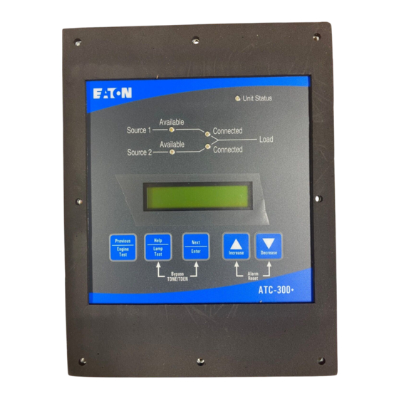
Preparing the ATC-300+ .............................................................................................................. 11
Preparing the ATC-900 ................................................................................................................. 11
This document will go over the procedure for configuring a PXG-1000, ELC-CAENET, and RAC for
use in an ATS controller network. Currently supported controllers are ATC-300+ and ATC-900.
11/14/2024
IB01602080E
Page | 1
Advertisement
Table of Contents

Related Manuals for Eaton PXG-1000


Summary of Contents for Eaton PXG-1000
-
Page 1: Table Of Contents
Configuring an ATS RAC ......................9 Preparing the ATC-300+ ......................11 Preparing the ATC-900 ......................... 11 This document will go over the procedure for configuring a PXG-1000, ELC-CAENET, and RAC for use in an ATS controller network. Currently supported controllers are ATC-300+ and ATC-900. 11/14/2024... -
Page 2: Preparing A Pxg-1000 Gateway
Preparing a PXG-1000 Gateway 1. Connect the PXG gateway to your PC via Ethernet cable and power the unit up. 2. Open a web browser and navigate to the PXG’s IP address. The default IP for LAN A is The default IP for LAN B is: 3. - Page 3 Once you have entered your PXG’s network info, click “Save Changes” in the upper right- hand corner of the screen to upload your settings. 11/14/2024 IB01602080E Page | 3...
- Page 4 Communications Port Setup Click the “Devices” button on the left navigation bar: 2. Click the ‘gear’ icon next to the COM port on whichever PXG-1000 COM port the RS-485 wiring from your ATC controller is connected to. (Continued on next page)
- Page 5 A settings bar will open on the right side of the screen. Enter the Baud Rate, Stop Bits, and Parity: Note these must match the coms settings of the devices on that com port (see the ATC-300+ or ATC- 900 controller IB for help on setting the coms settings for your controllers).
-
Page 6: Preparing An Elc-Caenet Module
Preparing an ELC-CAENET Module • Download and install ECISoft from Eaton’s website. • Connect your ELC-CAENET module to your PC either via the serial port or the Ethernet port on the module. • Connect 24 Vdc to the CAENET using the provided wiring connector. - Page 7 • You should see a picture of your ELC-CAENET module (see below): • Double-click the module picture and it will take you to the module configuration menu. • Click on the “Basic” tab. • Configure your IP Address, Netmask, and Gateway IP addresses based on the customer’s desired network configuration.
- Page 8 • Set COM2 Mode (RS-485) to “Modbus RTU Master”. • Baud rate, parity, stop bits must match your ATC controller settings. o Baudrate: ATC-300+/900 have adjustable baud rate setpoints (minimum of 9600). o Parity and Stop Bits: If you are using an ATC-300+, the Parity is always “None”, and the Stop Bits is always “1”.
-
Page 9: Configuring An Ats Rac
It is possible to monitor any number of ATS switches with ATC-300+ and ATC-900 controllers (up to 8 switches per RAC) over Ethernet networks. Both the ELC-CAENET and the PXG-1000 provide an easy-to-manage “Modbus RTU” to “Modbus TCP/IP” gateway feature. - Page 10 . Your RAC should be configured for Ethernet communications now! Press the Home button. 3. Press the run button on the HMI Setup Screen and your RAC should reboot. 11/14/2024 IB01602080E Page | 10...
-
Page 11: Preparing The Atc-300
Preparing the ATC-300+ The only options that need to be changed on an ATC-300+ are “Address” and “Baud Rate”. Navigate to the Address setpoint and set this to one of the following: • If you have a single-view RAC (programmed with RAC_E firmware) set the Modbus Address to 1.
Need help?
Do you have a question about the PXG-1000 and is the answer not in the manual?
Questions and answers