
Related Manuals for Eaton ELC Series


Summary of Contents for Eaton ELC Series
- Page 1 2010-12-03 5011696801-ETP1 Eaton Logic Controller Ethernet Distributed I/O Adapter Module INSTRUCTION SHEET [Applicable Distributed I/O Adapter Module] ELC-CAENET IL05006001E 002-1214120-01...
- Page 2 Thank you for choosing the Eaton Logic Controller (ELC) series products. The ELC-CAENET is an Ethernet distributed I/O adapter module that connects ELC I/O modules to Modbus TCP or EtherNet/IP networks. The adapter provides I/O and module diagnostic information to Modbus TCP or EtherNet/IP scanners.
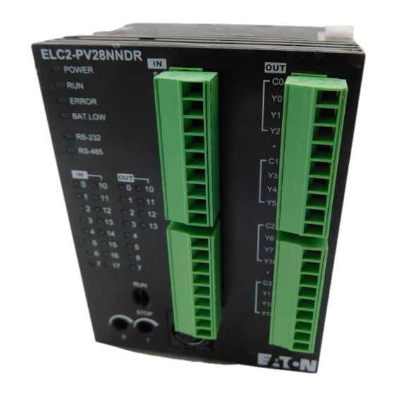
- Page 3 1. POWER indicator 12. RS-485 communication port 2. RUN indicator 13. Extension module positioning hole 3. BAT.LOW indicator 14. Nameplate 4. RUN / STOP switch 15. Extension port 5. RS-232 indicator 16. DIN rail (35mm) 6. RS-485 indicator 17. Extension module fixing clip 18.
-
Page 4: Function Specifications
Signal Definition Receive data Transmit data Ground RS-485 PIN Definition: Feed-through Terminal Signal Definition Signal Ground Negative pole for data Positive pole for data Function Specifications Network Interface Interface RJ-45 with Auto MDI/MDIX Number of ports 1 Port Transmission method IEEE 802.3, IEEE 802.3u Transmission cable Category 5e (TIA/EIA-568-A,TIA/EIA-568-B) -
Page 5: Installation
Environmental Specifications ESD (IEC 61131-2, IEC 61000-4-2): 8KV Air Discharge EFT (IEC 61131-2, IEC 61000-4-4): Power Line:±2KV, Digital Input: ±2KV, Communication I/O: ±2KV RS (IEC 61131-2, IEC 61000-4-3): 80MHz ~ 100MHz, Noise Immunity 10V/m. 1.4GHz ~ 2.0GHz, 10V/m Conducted Susceptibility Test (EN61000-4-6, IEC61131-2 9.10): 150KHz ~ 80MHz, 3V/m Surge Test (Biwave IEC61132-2, IEC61000-4-5): Power line 0.5KV DM, Ethernet 0.5KV CM, RS-485 0.5KV CM... -
Page 6: Function Codes Supported
35mm DIN rail Modbus Parameter Function Codes Supported Function code Explanation Devices supported 0x01 Read Coil RX, RY, T, R, C 0x02 Read discrete input RX, RY, T, R, C 0x03 Read holding register BR, T, C, RCR 0x05 Write Single coil RY, T, R, C 0x06 Write single holding register... -
Page 7: Ethernet/Ip Parameters
Holding Register Device Modbus address 6-digit Modbus Explanation Number type (Hex) address (Dec) Basic Register 0x0000~0x0040 400001~400064 Timer (word) 0x1600~0x160F 405633~405649 Counter (word) 0x1E00~0x1E0F 407681~407696 CR of extension 0x3000~0x3190 412289~412689 modules EtherNet/IP Parameters Service Codes Supported Service code Explanation Object supported 0x05 Reset Identity Object... -
Page 8: Led Indication
Discrete Input Object 0x08 #1 ~ #256 256 Input points* Discrete Output Object 0x09 #1 ~ #256 256 Output points* BR Object 0x64 #1 ~ #64 64 BR registers RCR Object 0x65 #1 ~ #400 400 RCR registers TCP/IP Interface Object 0xF5 #1 ~ #6 TCP/IP Parameters*... -
Page 9: Troubleshooting
LED Status Indication How to deal with Yellow Transmission speed: Check if the RJ-45 cable is constantly OFF 10Mbps properly connected. Codes in Digital Display Code Status Indication Solution Node address of 0 ~ FF ELC-CAENET is operating normally Flash Returning to default settings Flash ELC-CAENET is booting. - Page 10 Abnormality Cause How to deal with Check that the RJ45 connector is RJ-45 poor contact properly connected to the Ethernet RJ-45 port. Check if the RJ-45 cable is The module is not correctly connected to the connected to the network network.
Need help?
Do you have a question about the ELC Series and is the answer not in the manual?
Questions and answers