
Related Manuals for 3M DBI-SALA EZ-Line


Summary of Contents for 3M DBI-SALA EZ-Line
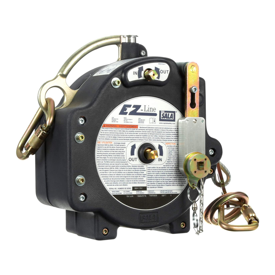
- Page 1 EZ-LinE OSHA 1910.140 OSHA 1926.502 Horizontal Lifeline System USER INSTRUCTIONS 5902346 R Figure 1 - Product Overview 7605060 © 3M 2021...
-
Page 2: Safety Information
Never exceed the maximum free fall distance specified for your Fall Protection equipment. Do not use any Fall Protection equipment that fails inspection, or if you have concerns about the use or suitability of the equipment. Contact 3M Technical Services with any questions. -
Page 3: Product Overview
Always ensure you are using the latest revision of your 3M instruction manual. Visit the 3M website or contact 3M Technical Services for updated instruction manuals. If you have any questions about the product or this instruction manual, please contact 3M Technical Services. The contact information for 3M Fall Protection is provided on the back cover of this instruction manual. -
Page 4: Component Specifications
Prior to installation and use of this equipment, record the product identification information from the ID label in the Inspection and Maintenance Log (Table 2) at the back of this manual. Table 1 – Product Specifications System Specifications: Capacity: Two persons maximum per span, with a combined weight (including clothing, tools, etc.) of no more than 310 lb. -
Page 5: Product Application
Hazards may include, but are not limited to: high heat, chemicals, corrosive environments, high voltage power lines, explosive or toxic gases, moving machinery, sharp edges, or overhead materials that may fall and contact the user or equipment. Contact 3M Technical Services for further clarification. - Page 6 MAKING CONNECTIONS: All connections must be compatible in size, shape, and strength. See Figure 4 for examples of inappropriate connections. Do not attach snap hooks and carabiners: To a D-Ring to which another connector is attached. In a manner that would result in a load on the gate. Large-throat snap hooks should not be connected to standard- size D-Rings or other connecting elements, unless the snap hook has a gate strength of 16 kN (3,600 lbf) or greater.
-
Page 7: Installation
INSTALLATION OVERVIEW: Installing a Horizontal Lifeline (HLL) System is a multi-step procedure that requires planning and awareness of the worksite. In summary, the basic procedure for installing the HLL System is as follows: 1. Prepare the anchorage connection points for the system. 2. - Page 8 Free fall is measured from the top of the user’s D-ring before a fall to the top of that same D-ring when the lanyard tightens during a fall. 3M Fall Protection shares the following method for measuring free fall in a system: Measuring free fall distance for an HLL: Connect one end of the lanyard to the HLL.
- Page 9 Figure 8 - Fall Clearance for Energy-Absorbing Lanyards ≤ 310 lb. (140 kg) FF = 6.0 ft. € € (1.83 m) ≤ 10 ft. 12 ft. 3 in. 13 ft. 4 in. (3.05 m) (3.72 m) (4.06 m) ≤ 20 ft. 13 ft.
- Page 10 To determine Required Fall Clearance for Self-Retracting Devices, refer to the following sections: A. SETBACK DISTANCE: When calculating fall clearance with an SRD, 3M Fall Protection defines two different application types based on the physical set-up of the system. See Figure 11 for an illustration of Setback Distance (X) and HLL System Height (H).
- Page 11 Figure 9 - Fall Clearance for SRDs (Small System Setback) System Span System Height Setback Distance SRD Retracted Length Required Fall Clearance € ≤ 310 lb. (140 kg) 0 ft. - <3 ft. 3 ft. - <5 ft. 5 ft. - <6.5 ft. ≥6.5 ft.
- Page 12 Figure 10 - Fall Clearance for SRDs (Large System Setback) ≤ 310 lb. (140 kg) € € ≤ 10 ft. 11 ft. 11 in. 12 ft. 4 in. (3.05 m) (3.64 m) (3.77 m) ≤ 20 ft. 13 ft. 1 in. 13 ft.
- Page 13 Handle. When the Crank Handle is released, it should return to its original position in line with the crank body. For 3M Rooftop Anchor installations, the wire rope should be tensioned only enough to raise it slightly above the working surface.
- Page 14 Figure 12 - Installing the HLL System...
- Page 15 Figure 13 - Removing the HLL System Figure 14 - System Applications Figure 15 - Anchorage Requirements...
- Page 16 In multiple-span HLL systems designed under ANSI Z359.6 or CSA Z259.16 to permit multiple users in multiple spans, it is the responsibility of the Qualified Person (and not of 3M) to evaluate and document the design considerations and details which ensure a single event or circumstance will not cause multiple users in multiple spans to fall within a very short period of time.
-
Page 17: Maintenance, Service, And Storage
Ensure parts are thoroughly rinsed with clean water. SERVICE: Only 3M or parties authorized in writing by 3M may make repairs to this equipment. STORAGE AND TRANSPORT: When not in use, store and transport the product and associated fall protection equipment in a cool, dry, clean environment out of direct sunlight. - Page 18 Figure 16 - Product Labels...
-
Page 19: Inspection Procedure
Inspect the wire rope for rust, corrosion, broken wires, or other obvious faults. Wire Rope must be replaced by a 3M authorized service center if there are six or more randomly distributed broken wires in one lay, or three or more broken wires in one strand in one lay. - Page 21 EZ-LINE OSHA 1910.140 OSHA 1926.502 Sistema de anticaídas horizontales INSTRUCCIONES DE USO Protección contra 5902346 R caídas Figura 1: Descripción general del producto 7605060 © 3M 2021...
-
Page 22: Información De Seguridad
Este producto se utiliza como parte de un sistema completo de protección contra caídas. 3M no aprueba su uso para ninguna otra aplicación, incluidas, entre otras, la manipulación de materiales, las actividades de recreación o relacionadas con el deporte, u otras actividades no descritas en estas instrucciones, ya que podrían ocasionarse lesiones graves o la muerte. -
Page 23: Descripción General Del Producto
DESCRIPCIÓN GENERAL DEL PRODUCTO: La Figura 1 ilustra el sistema de línea de vida horizontal (HLL, por sus siglas en inglés) 3M™ DBI-SALA® EZ-Line™. El sistema de HLL está asegurado entre dos puntos de anclaje y brinda conexiones para hasta dos usuarios como parte de un sistema de detención de caídas o de retención ante ese evento. - Page 24 Antes de instalar y utilizar este equipo, anote la información de identificación del producto que figura en la etiqueta de identificación que se encuentra en el Registro de inspección y mantenimiento (Tabla 2), en la parte posterior de este manual. Tabla 1 –...
-
Page 25: Requisitos Del Sistema
Los conectores deben estar completamente cerrados y bloqueados durante el uso. Los conectores de 3M (ganchos de seguridad y mosquetones) están diseñados para el uso exclusivo que se especifica en los manuales de instrucciones. Asegúrese de que los conectores sean compatibles con los componentes del sistema a los que están conectados. No use un equipo que no sea compatible. - Page 26 CÓMO HACER CONEXIONES: Las conexiones deben ser compatibles en tamaño, forma y resistencia. Consulte la Figura 4 para obtener ejemplos de conexiones incorrectas. Los ganchos de seguridad y mosquetones no deben sujetarse: A un anillo en D al que se ha fijado otro conector. De manera tal que se produzca una carga sobre la abertura.
-
Page 27: Instalación
INSTALACIÓN ASPECTOS GENERALES: La instalación de un sistema de línea de vida horizontal (HLL) es un procedimiento de varios pasos que requiere planificación y conocimiento del lugar de trabajo. En resumen, el procedimiento básico para instalar el sistema de HLL es el siguiente: 1. - Page 28 La caída libre se mide desde la parte superior del anillo en D del usuario antes de una caída hasta la parte superior del mismo anillo en D cuando el cordón se ajusta durante una caída. La División de Protección contra Caídas de 3M comparte el siguiente método para medir la caída libre en un sistema:...
- Page 29 Figura 8: Espacio libre de caída para eslingas absorbedoras de energía ≤ 310 lb (140 kg) FF = 6,0 ft € € (1,83 m) ≤ 10 ft 12 ft 3 in 13 ft 4 in (3,05 m) (3,72 m) (4,06 m) ≤ 20 ft 13 ft 8 in 15 ft 10 in (6,10 m)
- Page 30 A. DISTANCIA DE RETROCESO: Al calcular el espacio libre de caída con un SRD, la división de Protección contra Caídas de 3M define dos tipos de aplicaciones diferentes según la configuración física del sistema. Consulte la Figura 11 para ver una ilustración de la distancia de retroceso (X) y la altura del sistema de HLL (H).
- Page 31 Figura 9: Espacio libre de caída para los SRD (retroceso de sistema pequeño) Tramo del sistema Altura del sistema Distancia de retiro Longitud del SRD retraído Espacio libre de caída requerido € ≤ 310 lb (140 kg) 0 ft - <3 ft 3 ft - <5 ft 5 ft - <6,5 ft ≥6,5 ft ≤...
- Page 32 Figura 10: Espacio libre de caída para los SRD (retroceso de sistema grande) ≤ 310 lb (140 kg) € € ≤ 10 ft 11 ft 11 in 12 ft 4 in (3,05 m) (3,64 m) (3,77 m) ≤ 20 ft 13 ft 1 in 13 ft 9 in Tramo del sistema (6,10 m)
- Page 33 Cuando se suelta la manivela, esta debe volver a su posición original en línea con el cuerpo de la manivela. Para las instalaciones de anclajes de techo 3M, el cable de acero debe tensarse solo lo suficiente para elevarlo ligeramente por encima de la superficie de trabajo.
- Page 34 Figura 12: Instalación del sistema de HLL...
- Page 35 Figura 13: Extracción del sistema de HLL Figura 14: Aplicaciones del sistema Figura 15: Requisitos de anclaje...
- Page 36 En los sistemas de HLL de varios tramos, diseñados de conformidad con los estándares ANSI Z359.6 o CSA Z259.16 para permitir varios usuarios en varios tramos, es responsabilidad del instalador (y no de 3M) incluir en la documentación del sistema las consideraciones de diseño y los detalles que garantizan que un único evento o circunstancia no causarían la caída de varios usuarios en...
-
Page 37: Mantenimiento, Reparación Y Almacenamiento
LIMPIEZA: Limpie en forma periódica los componentes metálicos del producto con un pincel suave, agua tibia y una solución jabonosa suave. Asegúrese de enjuagar bien las piezas con agua limpia. TAREAS DE MANTENIMIENTO O REPARACIÓN: Solo 3M o las entidades autorizadas por escrito por 3M pueden hacer reparaciones a este equipo. - Page 38 Figura 16: Etiquetas de productos...
- Page 39 Inspeccione el cable para verificar si hay corrosión, alambres rotos u otros defectos evidentes. Un centro de servicio autorizado por 3M debe reemplazar el cable de acero si hay seis o más alambres rotos distribuidos al azar en un paso, o tres o más alambres rotos en una hebra de un paso.
- Page 40 3M. 3M será el único capaz de determinar la condición del producto y las opciones de la garantía. This warranty applies only to the original purchaser and is the only warranty applicable to 3M’s fall protection products.
Need help?
Do you have a question about the DBI-SALA EZ-Line and is the answer not in the manual?
Questions and answers