Table of Contents
Advertisement
Quick Links
OSHA 1926.502
A
A
1
8530869
8530870
2
3
8530871
4
8530872
5
8530873
EN 795:2012
Regulation (EU) 2016/425
CE Type Test
CE Production Quality Control
No. 2797
BSI
The Netherlands B.V.
The Netherlands B.V.
Say Building
Say Building
John M. Keynesplein 9
John M. Keynesplein 9
1066 EP
Amsterdam
Netherlands
Netherlands
OSHA 1910.140
1
2
3
3M
Type E
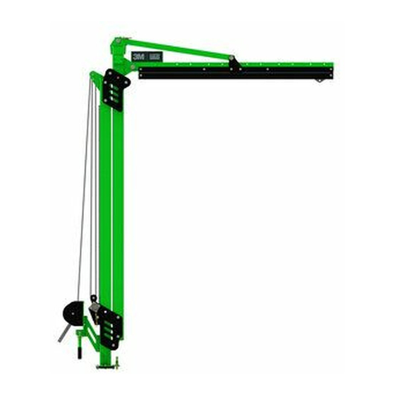
Modular Jib System M100
No. 2797
BSI
1066 EP
Amsterdam
1
1
8530874
1
8530875
1
8530876
B
1
8530877
2
8530882
2
8530883
2
8530884
W
1
A
4
5
DBI-SALA
Flexiguard
TM
®
Adjustable Jib Boom
USER INSTRUCTIONS
5908371 Rev. C
W
H
7.5 ft.
10.0 ft. - 15.0 ft.
(2.3 m)
(3.0 m - 4.6 m)
7.5 ft.
12.5 ft. - 20.0 ft.
(2.3 m)
(3.8 m - 6.1 m)
7.5 ft.
15.0 ft. - 25.0 ft.
(2.3 m)
(4.6 m - 7.6 m)
7.5 ft.
17.5 ft. - 30.0 ft.
(2.3 m)
(5.3 m - 9.1 m)
7.5 ft.
15.0 ft. - 20.0 ft.
(2.3 m)
(4.6 m - 6.1 m)
7.5 ft.
20.0 ft. - 25.0 ft.
(2.3 m)
(6.1 m - 7.6 m)
7.5 ft.
25.0 ft. - 30.0 ft.
(2.3 m)
(7.6 m - 9.1 m)
2
H
A
C
8530911
TM
lb. (kg)
568 lb.
(258 kg)
638 lb.
(289 kg)
727 lb.
(330 kg)
805 lb.
(365 kg)
504 lb.
(229 kg)
582 lb.
(264 kg)
660 lb.
(299 kg)
W
H
© 3M 2020
Advertisement
Table of Contents

Related Manuals for 3M DBI-SALA FlexiGuard M100


Summary of Contents for 3M DBI-SALA FlexiGuard M100
- Page 1 582 lb. 8530883 (2.3 m) (6.1 m - 7.6 m) (264 kg) 7.5 ft. 25.0 ft. - 30.0 ft. 660 lb. 8530884 (2.3 m) (7.6 m - 9.1 m) (299 kg) 8530869 8530911 8530870 8530871 8530872 8530873 © 3M 2020...
- Page 4 = 0° = 360°...
- Page 9 ≤ 140 kg (1350 lbs.) (310 lbs.) = 0° lb.(kg) 8530874 568 lbs. (258 kg) 3M.com/FallProtection 8530875 638 lbs. (289 kg) Red Wing, MN 55066, USA 8530876 727 lbs. (330 kg) 8530877 805 lbs. (365 kg) Serial no / N° de serie: 9514429 Rev.
-
Page 10: Safety Information
Ensure there is adequate fall clearance when working at height. Never modify or alter your fall protection equipment. Only 3M or parties authorized in by 3M may make repairs to the equipment. Prior to use of fall protection equipment, ensure a rescue plan is in place which allows for prompt rescue if a fall incident occurs. -
Page 11: Product Description
Prior to installation and use of this equipment, record the product identification information from the ID label in the Inspection and Maintenance Log (Table 2) at the back of this manual. Always ensure you are using the latest revision of your 3M instruction manual. Visit the 3M website or contact 3M Technical Services for updated instruction manuals. -
Page 12: Product Application
Contact 3M if you have any questions about compatibility. Connectors must comply with EN 362. Connectors must be compatible with the anchorage or other system components. - Page 13 3M connectors (snap hooks and carabiners) are designed to be used only as specified in each product’s user’s instructions. See Figure 6 for examples of inappropriate connections. Do not connect snap hooks and carabiners: To a D-ring to which another connector is attached.
-
Page 14: Installation
INSTALLATION PLANNING: Plan your Fall Protection system prior to installation of the Jib Boom. Account for all factors that may affect your safety before, during and after a fall. Consider all requirements, limitations, and specifications defined in Section 2 and Table 1. PLACING THE JIB BOOM: Before the Jib Boom can be used, it must be secured to a Jib Base. -
Page 15: Maintenance, Service, And Storage
Ensure parts are thoroughly rinsed with clean water. SERVICE: Only 3M or parties authorized in writing by 3M may make repairs to this equipment. STORAGE: If applicable, store the Jib Boom and associated Fall Protection equipment in a cool, dry, clean environment out of direct sunlight. - Page 16 Adjustment Winch (G) has no frays or tearing. Ensure the locking assembly engages. Winch Assembly Inspect the Winch Assembly per 3M instruction manual 8511324. Rollers and Bearings Grease the Rollers (A) and Bearings (B) of the Adjustable Upright Assembly for (Figure 12) B1 Jib Boom models.
- Page 17 Kontrollera att vajern till justeringsvinschen (G) inte är fransad eller har brott. Se till att låsenheten hakar i. Vinschenhet Kontrollera vinschenheten enligt 3M:s bruksanvisning 8511324. Rullar och lager Smörj rullarna (A) och lagren (B) på pelarenheten för B1-svängbomsmodeller.
- Page 18 RAJATTU KORVAUS: Kirjallisella 3M:lle lähetetyllä ilmoituksella 3M korjaa tai vaihtaa kaikki tuotteet, par 3M comme souff rant d’un défaut de fabrication en usine ou de matériaux. 3M se réserve le droit d’exiger joissa on 3M:n määrittelemä valmistus- tai materiaalivirhe. 3M pidättää oikeuden vaatia tuotetta que le produit lui soit retourné...
- Page 19 Distributed by Engineered Fall Protection 3833 SALA Way Sales@EngineeredFallProtection.com Red Wing, MN www.EngineeredFallProtection.com 55066-5005 Tel: (314) 492-4422 I S O EU DECLARATION OF CONFORMITY: 9 0 0 1 FM534873...
- Page 20 3M™ DBI-SALA® Flexiguard™ OSHA Modular Jib Systems M100 Technical Data Sheet Pack 5908525 Rev. C Callout Technical Data Sheet Description Page 8530874 10 ft.–15 ft. (3.0 m–4.6 m) Jib Arm Adjustable 8530875 12.5 ft.–20 ft. (3.8 m–6.1 m) Jib Arm Adjustable 8530876 15 ft.–25 ft.
- Page 21 The M100 Modular Jib Arm is designed to provide anchorage connection points for a Fall Protection system. For more information on product installation, refer to the 3M instruction manual for the M100 Jib Arm (5908371). Standards: EN795:2012 Type E, OSHA 1910.140, OSHA 1926.502 10.32 ft.
- Page 22 Spacer Steel 9515138 Bearings Steel 8550327 Narrow Roller Nylon 8550125 Rotation Stop Steel 9514703 Side Roller Nylon 9515111 3M Label Polyester 8550215 Narrow Roller 304 Stainless Spacer Steel 9515101 Rotation Label Polyester 8549930 Winch Steel 9514429 ID Label Polyester...
- Page 23 The M100 Modular Jib Arm is designed to provide anchorage connection points for a Fall Protection system. For more information on product installation, refer to the 3M instrucction manual for the M100 Jib Arm (5908371). Standards: EN795:2012 Type E, OSHA 1910.140, OSHA 1926.502 9.70 ft.
- Page 24 TECHNICAL DATA SHEET: 8530882-8530884 Part Description Material Quantity Part Description Material Quantity Number Number 8521711 Trolley Stainless Steel, 9515111 3M Label Polyester Steel, Nylon 9515101 Rotation Label Polyester 8549931 Rescue Mount Steel Channel 8550125 Rotation Stop Steel 8550238 Channel Steel...
- Page 25 TECHNICAL DATA SHEET: 8530869, 8530870 APPLICATION: The Counterweight Base is designed to be filled with concrete and used as a mounting point for 3M™ DBI-SALA® Flexiguard™ Modular Jib System M100. For more information on product installation, refer to the 3M instruction manual for M100 Concrete Base (5908373).
- Page 26 M100 Counterweight Base Working Area TECHNICAL DATA SHEET: 8530869, 8530870 APPLICATION: Refer to the diagram below for the working area of the M100 Concrete Base.
- Page 27 M100 Counterweight Base Accessories TECHNICAL DATA SHEET: 8530908, 8530914 Weight 8530908 152 lb. (69 kg) Component List Part Description Material Quantity Number 8510037 1/2” Washer Steel 8512460 1/2” X 1 1/4” Bolt Steel 8518432 1/2” x 1” Bolt Steel 8550153 Wheel Weldment Steel 8550155...
- Page 28 M100 Counterweight Base Center of Gravity TECHNICAL DATA SHEET: 8530869, 8530870 8530870 8530877 8530870 8530877 1,905 lbs. 5,000 lbs. .lb (kg) .lb (kg) (864 kg) (2,268 kg) 23” (84 cm) 45.0" (114.3 cm) 63.0" 63” (160 cm) (160.0 cm) 8530870 8530877 3,095 lbs.
- Page 29 TECHNICAL DATA SHEET: 8530871 APPLICATION: The Floor Mount Base is designed to be anchored to approved structures and used as a mounting point for the 3M approved Modular Jib System M100. For more information on product installation, refer to the 3M instruction manual for the M100 Floor Mount Base (5908370).
- Page 30 TECHNICAL DATA SHEET: 8530872, 8530918, 8530919 APPLICATION: The Flush Mount Base is designed to be anchored to approved structures and used as a mounting point for the 3M approved Modular Jib System M100. For more information on product installation, refer to the 3M instruction manual for the M100 Flush Mount Base (5908370).
- Page 31 M100 Floor Mount Bases Working Area TECHNICAL DATA SHEET: 8530871, 8530872 APPLICATION: Refer to the diagram below for the working area of the Floor Mount Bases.
-
Page 32: Supporting Structure
TECHNICAL DATA SHEET: 8530873 APPLICATION: The H-Base is designed to be used as a mounting point for 3M™ DBI-SALA® Flexiguard™ Modular Jib System M100. For more information on product installation, refer to the 3M instruction manual for the M100 H-Base (5908377). - Page 33 M100 H-Base Working Area TECHNICAL DATA SHEET: 8530873 APPLICATION: Refer to the diagram below for the working area of the M100 H-Base.
- Page 34 TECHNICAL DATA SHEET: 8530911 APPLICATION: The M100 Fork Pocket Kit is designed to transport the Adjustable Jib Boom. For more information on product installation, refer to the 3M instruction manual for the M100 Adjustable Jib Arm (5908371). Part Component Quantity...
- Page 35 Distributed by Engineered Fall Protection 3833 SALA Way Sales@EngineeredFallProtection.com Red Wing, MN 55066-5005 www.EngineeredFallProtection.com Tel: (314) 492-4422 I S O EU DECLARATION OF CONFORMITY: 9 0 0 1 FM534873...
- Page 36 3M™ DBI-SALA® FLEXIgUARD™ EN 795:2012 Modular Jib System M100 Type E Counterweight Base Regulation (EU) 2016/425 CE Type Test CE Production Quality Control No. 2797 No. 2797 The Netherlands B.V. The Netherlands B.V. USER INSTRUCTIONS Say Building Say Building John M. Keynesplein 9 John M.
- Page 37 4,000 psi (30 MPa) 0.69 yd (0.53 m 8530914...
- Page 38 = 236° = 0°...
- Page 39 45” 23” (114 cm) (84 cm) 63" (160 cm) 30" (76 cm) 60" (152 cm) 27.5" 8.0" 63” (160 cm) (69.9 cm) (20.3 cm) 30” (76 cm) 60” (152 cm) 55.0" (139.7 cm) 16" (40.6 cm)
- Page 40 + / - 1°...
- Page 42 Serial no / N° de serie: 9514429 Rev. B 2797 OSHA 1926.502 / 1910.140 EN795:2012 "TYPE E" 4,000 PSI (30 MPa) + / - 1° ≤ 7.5' (2.3m) 23” (84 cm) lb.(kg) lb.(kg) lb.(kg) lb.(kg) 3,095 lbs. (1,404 kg) 1,100 lbs. (499 kg) ≤...
-
Page 43: Safety Information
Ensure there is adequate fall clearance when working at height. Never modify or alter your fall protection equipment. Only 3M or parties authorized in by 3M may make repairs to the equipment. Prior to use of fall protection equipment, ensure a rescue plan is in place which allows for prompt rescue if a fall incident occurs. -
Page 44: Installation
The Counterweight Base can only be used with the 3M Modular Jib System M100 manufactured by 3M. Do not attempt to use the Counterweight Base without first consulting the User Instructions for the 3M Modular Jib System M100 (5908371). - Page 45 PREPARING THE JIB BASE (8530869): Counterweight Base model 8530870 ships already filled. Counterweight Base model 8530869, however, will need to be prepared before use. See Figure 2 for reference. To prepare the Jib Base: Fill the Counterweight Box with 0.69 yd (0.53 m ) of concrete (A) with a rating of 4,000 psi (30 MPa) to the top of the box.
-
Page 46: Maintenance, Service, And Storage
DEFECTS: If the Counterweight Base cannot be returned to service because of an existing defect or unsafe condition, then either destroy the system or contact 3M or a 3M-authorized service center about possible repair. PRODUCT LIFE: The functional life of the Counterweight Base is determined by work conditions and maintenance. As long as the product passes inspection criteria, it may remain in service. - Page 47 Table 2 – Inspection and Maintenance Log Inspection Date: Inspected By: Competent Components: Inspection: User Person (See Section 3 for Inspection Frequency) Counterweight Inspect the Counterweight Base for structural defects or damage including, but Base not limited to: bends, corrosion, and cracks. Verify that there is no missing concrete from the Counterweight Box.
- Page 48 RAJATTU KORVAUS: Kirjallisella 3M:lle lähetetyllä ilmoituksella 3M korjaa tai vaihtaa kaikki tuotteet, par 3M comme souff rant d’un défaut de fabrication en usine ou de matériaux. 3M se réserve le droit d’exiger joissa on 3M:n määrittelemä valmistus- tai materiaalivirhe. 3M pidättää oikeuden vaatia tuotetta que le produit lui soit retourné...
- Page 49 Distributed by Engineered Fall Protection 3833 SALA Way Sales@EngineeredFallProtection.com Red Wing, MN 55066-5005 www.EngineeredFallProtection.com Tel: (314) 492-4422 I S O EU DECLARATION OF CONFORMITY: 9 0 0 1 FM534873...
-
Page 50: Installation Instructions
OSHA 1926:502 En795: 2012 3M™ DBI-sala® FlEXIguarD™ OSHA 1910:140 type a Modular Jib system M100 looR ount InstallatIon InstructIons 5908370 R 8530871 ≤7.5 ft 43.30 in. 15.75 in. 8530871 (2.3 m) (1.10 m) (0.40 m) 8530872 ≤7.5 ft 15 in. - Page 52 +/- 1° 7/8 in. (22 mm) 6.88 in. 6.88 in. (175 mm) (175 mm) 6.88 in. (175 mm) 13.75 in. (349 mm) 6.88 in. (175 mm) 13.75 in. (349 mm)
- Page 53 11 in. (279 mm) 7/8 in. 5.5 in. (22 mm) (140 mm) +/- 1° +/- 1° 11 in. (279 mm) 5.5 in. (140 mm) 22.75 in. (578 mm) Ø 5.06 in. (130 mm)
- Page 55 8530872 8530871 EN795:2012 "TYPE A" OSHA 1926.502 & 1910.140 ≤ 7.5' (2.3m) 9515113 Rev. A...
-
Page 56: Safety Information
Ensure there is adequate fall clearance when working at height. Never modify or alter your fall protection equipment. Only 3M or parties authorized in by 3M may make repairs to the equipment. Prior to use of fall protection equipment, ensure a rescue plan is in place which allows for prompt rescue if a fall incident occurs. -
Page 57: Product Application
This Floor Mount Base can only be used with the 3M Modular Jib System M100 manufactured by 3M. Do not attempt to use the Floor Mount Base without first consulting the user instruction 5908371 for the 3M Modular Jib System M100. -
Page 58: Installation
Lower the Mounting Post until the Rotation Block (A) is resting in the Locking Slot (B) in the Base (Figure 5.1). • Install the 3M Modular Jib System M100 onto the Base (Figure 5.2). • Apply grease to grease fitting located on the Jib (Figure 5.3). -
Page 59: Labels And Markings
CLEANING: Periodically clean the metal components of the Floor Mount Base with a soft brush, warm water, and a mild soap solution. Ensure parts are thoroughly rinsed with clean water. SERVICE: Only 3M or parties authorized in writing by 3M may make repairs to this equipment. LABELS and MARKINGS: LABELS: Figure 7 illustrates labels on the Floor Mount Base. - Page 60 Table 2 – Inspection and Maintenance Log Inspection Date: Inspected By: Competent Components: Inspection: User Person (See Section 4 for Inspection Frequency) Floor Mount Base Inspect the Floor Mount Base for structural defects or damage including bends, (Figure 1) corrosion, etc. Inspect the mounting fasteners to ensure they are tightened to the proper torque value, as specified by the fastener manufacturer.
- Page 61 RAJATTU KORVAUS: Kirjallisella 3M:lle lähetetyllä ilmoituksella 3M korjaa tai vaihtaa kaikki tuotteet, par 3M comme souff rant d’un défaut de fabrication en usine ou de matériaux. 3M se réserve le droit d’exiger joissa on 3M:n määrittelemä valmistus- tai materiaalivirhe. 3M pidättää oikeuden vaatia tuotetta que le produit lui soit retourné...
- Page 62 Distributed by Engineered Fall Protection 3833 SALA Way Sales@EngineeredFallProtection.com Red Wing, MN 55066-5005 www.EngineeredFallProtection.com Tel: (314) 492-4422 I S O EU DECLARATION OF CONFORMITY: 9 0 0 1 FM534873...
- Page 63 John M. Keynesplein 9 1066 EP 1066 EP USER INSTRUCTIONS Amsterdam Amsterdam Netherlands Netherlands 5908377 Rev. C OSHA 1910.140 OSHA 1926.502 8530873 15 ft. (4.6 m) 15 ft. (4.6 m) 3.6 ft. (1.1 m) ≤ 7.5 ft. (2.3 m) © 3M 2020...
- Page 66 = 0° x = ±1°...
- Page 67 Mfrd. (yr, mo) Model No.: Fabr. (aa, mm) N° de Modelo: 3M.com/FallProtection Red Wing, MN 55066, USA Serial no / N° de serie: 9514429 Rev. B...
- Page 68 Ensure there is adequate fall clearance when working at height. Never modify or alter your fall protection equipment. Only 3M or parties authorized in by 3M may make repairs to the equipment. Prior to use of fall protection equipment, ensure a rescue plan is in place which allows for prompt rescue if a fall incident occurs.
- Page 69 Figure 2 illustrates components of the H-Base. See Table 1 for Component Specifications. The Hitch Ball Post (A) is the receiver to mount the approved 3M Flexiguard M100 Mast. The Outrigger Legs (D) provide support for the H-Base and are connected by the Main Center Base (B) where the Level Indicators (C) are located.
-
Page 70: Maintenance, Servicing, And Storage
DEFECTS: If the H-Base cannot be returned to service because of an existing defect or unsafe condition, then either destroy the system or contact 3M or a 3M-authorized service center about possible repair. PRODUCT LIFE: The functional life of the H-Base is determined by work conditions and maintenance. As long as the product passes inspection criteria, it may remain in service. - Page 71 SERVICE: Only 3M or parties authorized in writing by 3M may make repairs to this equipment. STORAGE: If applicable, store the H-Base and associated Fall Protection equipment in a cool, dry, clean environment out of direct sunlight. Avoid areas where chemical vapors may exist. Thoroughly inspect components after extended storage.
- Page 72 Table 2 – Inspection and Maintenance Log Inspection Date: Inspected By: Competent Components: Inspection: User Person (See Section 1 for Inspection Frequency) Outrigger Base Ensure that the outrigger legs are not bent or cracked and that all hardware is (Figure 2) present and securely tightened.
- Page 73 LIMITED REMEDY: Upon written notice to 3M, 3M will repair or replace any product determined by par 3M comme souff rant d’un défaut de fabrication en usine ou de matériaux. 3M se réserve le droit d’exiger 3M to have a factory defect in workmanship or materials. 3M reserves the right to require product be que le produit lui soit retourné...
- Page 74 Distributed by Engineered Fall Protection 3833 SALA Way Sales@EngineeredFallProtection.com Red Wing, MN www.EngineeredFallProtection.com 55066-5005 Tel: (314) 492-4422 I S O EU DECLARATION OF CONFORMITY: 9 0 0 1 FM534873...
- Page 75 3M™ DBI-SALA FLexIGuArD™ OSHA 1926.502 OSHA 1910.140 ® M100 and M200 Jib System rescue Kit uSer INSTruCTIONS 5908376 rev. B 8530885 8530885 8530905 ≤ 7.5 ft. (2.3 m) 8530905 ≤ 15.0 ft. (4.6 m) © 3M 2020...
- Page 76 8530885 8530905...
- Page 77 8530885 8530905...
- Page 78 Mfrd. (yr, mo) Model No.: Fabr. (aa, mm) N° de Modelo: 3M.com/FallProtection Red Wing, MN 55066, USA Serial no / N° de serie: 9514429 Rev. B...
- Page 79 Before using this equipment, record the product identification information from the ID label in the “Inspection and Maintenance Log” at the back of this manual. Always ensure you are using the latest revision of your 3M instruction manual. Visit the 3M website or contact 3M Technical Services for updated instruction manuals.
- Page 80 Ensure parts are thoroughly rinsed with clean water. SERVICE: Only 3M or parties authorized in writing by 3M may make repairs to this equipment. STORAGE AND TRANSPORT: If applicable, store and transport the Rescue Kit and associated Fall Protection equipment in a cool, dry, clean environment out of direct sunlight.
- Page 81 Table 2 – Inspection and Maintenance Log Inspection Date: Inspected By: Competent Components: Inspection: User Person (See Section 1 for Inspection Frequency) □ □ Rescue Kit Inspect all components of the Rescue Kit for corrosion or damage such as cracks, bends, dents, or wear that could affect the strength and operation of the system.
- Page 82 LIMITED REMEDY: Upon written notice to 3M, 3M will repair or replace any product determined by défaut de fabrication en usine ou de matériaux, tel que déterminé par 3M. 3M se réserve le droit d’exiger le 3M to have a factory defect in workmanship or materials. 3M reserves the right to require product be retour du produit dans ses installations afi...
- Page 83 Distributed by Engineered Fall Protection 3833 SALA Way Sales@EngineeredFallProtection.com Red Wing, MN 55066-5005 www.EngineeredFallProtection.com Tel: (314) 492-4422 I S O EU DECLARATION OF CONFORMITY: 9 0 0 1 FM534873...
- Page 84 M100 Modular Jib System Rescue Kit Overview 8550354 M100 Winch Mount Bracket 8550142 M100 Upright Bracket 8550151 M100 Rail Bracket 8530905 M200 Modular Jib System Rescue Kit Overview 8550355 M200 Winch Mount Bracket 8550144 M200 Upright Bracket 8550147 M200 Rail Bracket © 3M 2020...
-
Page 85: System Specifications
The M100 Modular Jib System Rescue Kit includes accessories to the M100 Modular Jib System that allow the system to be used for Rescue applications. Refer to the listed data sheets for component specifications. For more information on product installation, refer to the 3M instruction manual for the Rescue Kit (5908376). Component Tech Data Sheet... -
Page 86: Part Specifications
M100 Winch Mount Bracket Technical Data Sheet: 8550354 APPLICATION: The Winch Mount Bracket is secured to the Jib Boom by means of the Offest Plates (B) at the bottom of the Bracket. A Rescue Winch may then be mounted to the Winch Mount (C) of the Bracket. Part Specifications: Net Weight 4.18 in. - Page 87 M100 Upright Bracket Technical Data Sheet: 8550142 APPLICATION: The Weldment (A) is secured to the Jib Boom by means of the 1/2” x 1” Bolts (H). The lifeline of the Rescue Winch is then threaded over the top of the Pulley (B) and onto the M100 Rail Bracket. Part Specifications: Net Weight 12.50 in.
- Page 88 M100 Rail Bracket Technical Data Sheet: 8550151 APPLICATION: The Rail Mount (A) connects to the Rail Assembly of the Jib Boom. The lifeline of the Rescue Winch is threaded over the Pulley (B) and down to the user. Part Specifications: Net Weight 7.50 in.
- Page 89 The M200 Modular Jib System Rescue Kit includes accessories to the M200 Modular Jib System that allow the system to be used for Rescue applications. Refer to the listed data sheets for component specifications. For more information on product installation, refer to the 3M instruction manual for the Rescue Kit (5908376). Component Tech Data Sheet...
- Page 90 M200 Winch Mount Bracket Technical Data Sheet: 8550355 APPLICATION: The Winch Mount Bracket is secured to the Jib Boom by means of the Offset Plates (B) at the bottom of the Bracket. A Rescue Winch may then be mounted to the Winch Mount (C) of the Bracket. Part Specifications: Net Weight 4.50 in.
- Page 91 M200 Upright Bracket Technical Data Sheet: 8550144 APPLICATION: The Weldment (A) is secured to the Jib Boom by means of the 1/2” x 1” Bolts (H). The lifeline of the Rescue Winch is then threaded over the top of the Pulley (B) and onto the M200 Rail Bracket. Part Specifications: Net Weight 12.88 in.
- Page 92 M200 Rail Bracket Technical Data Sheet: 8550147 APPLICATION: The Rail Mount (A) connects to the Rail Assembly of the Jib Boom. The lifeline of the Rescue Winch is threaded over the Pulley (B) and down to the user. Part Specifications: Net Weight 10.75 in.
- Page 93 LIMITED REMEDY: Upon written notice to 3M, 3M will repair or replace any product determined by 3M to have a factory defect in workmanship or materials. 3M reserves the right to require product be returned to its facility for evaluation of warranty claims. This warranty does not cover product damage due to wear, abuse, misuse, damage in transit, failure to maintain the product or other damage beyond 3M’s control.
Need help?
Do you have a question about the DBI-SALA FlexiGuard M100 and is the answer not in the manual?
Questions and answers