
Related Manuals for 3M DBI SALA EZ-Line


Summary of Contents for 3M DBI SALA EZ-Line
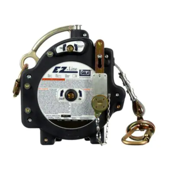
- Page 1 EZ-L OSHA 1910.140 OSHA 1926.502 Horizontal Lifeline System USER INSTRUCTION MANUAL 5902346 R 7605060 © 3M 2020...
- Page 4 4 ft. 5 ft. 6 ft. (.91 (1.22 m) (1.52 m) (1.83 m) (.91 m) (1.22 m) (1.52 m) (1.8 3m) ≤ 10.0 ft. 15.49 ft. 16.49 ft. 17.49 ft. 18.49 ft. 16.72 ft. 17.72 ft. 18.72 ft. 19.72 ft.
- Page 5 X ≤ 2 ft. or X ≤ Y € € ≤ 310 lb. (140 kg) ≤ 310 lb. (140 kg) 5 ft. ≤ A< 6.5 ft. 0 ft. ≤ A< 3 ft. A ≥ 6.5 ft. 5 ft. ≤ A <6.5 ft. 3 ft.
- Page 6 X > 2 ft. & X > Y € € € € 220 lb. ≤ 310 lb 310 lb 220 lb ≤ ≤ ≤ (100 kg) (140 kg) (140 kg) (100 kg) ≤10.0 ft. 12.22 ft ≤10.0 ft. 13.49 ft ≤10.0 ft.
-
Page 10: Safety Information
Ensure there is adequate fall clearance when working at height. Never modify or alter your fall protection equipment. Only 3M or parties authorized in writing by 3M may make repairs to the equipment. Prior to use of fall protection equipment, ensure a rescue plan is in place which allows for prompt rescue if a fall incident occurs. -
Page 11: Product Description
Prior to installation and use of this equipment, record the product identification information from the ID label in the Inspection and Maintenance Log (Table 2) at the back of this manual. Always ensure you are using the latest revision of your 3M instruction manual. Visit the 3M website or contact 3M Technical Services for updated instruction manuals. -
Page 12: Product Application
Hazards may include, but are not limited to: high heat, chemicals, corrosive environments, high voltage power lines, explosive or toxic gases, moving machinery, sharp edges, or overhead materials that may fall and contact the user or equipment. Contact 3M Technical Services for further clarification. - Page 13 Connectors must be fully closed and locked during use. 3M Connectors (snap hooks and carabiners) are designed to be used only as specified in each instruction manual. Ensure connectors are compatible with the system components to which they are connected. Do not use equipment that is non- compatible.
-
Page 14: Installation
3.2. Greater free fall distances will require more Fall Clearance. When the connecting subsystem used with the HLL system is a non-3M product, 1 ft. (0.3 m) of additional Fall Clearance must be added to the values in the Fall Clearance charts to account for unknown variation in product performance. - Page 15 B. SELF-RETRACTING DEVICES (SRDs): Any SRDs used with the HLL System must be approved for use with deformable anchorage systems. Retracted Length: SRDs should have a retracted length of 2 ft. (0.61 m) or less. For SRDs with a retracted length longer than 2 ft.
- Page 16 In multiple-span HLL systems designed under ANSI Z359.6 or CSA Z259.16 to permit multiple users in multiple spans, it is the responsibility of the Qualified Person (and not of 3M) to evaluate and document the design considerations and details which ensure a single event or circumstance will not cause multiple users in multiple spans to fall within a very short period of time.
- Page 17 • A common setup involving 3M Stanchion Posts places the HLL at a height 3 ft. (0.9 m) above the walking surface. A 6 ft. (1.8 m) lanyard used in combination with the Stanchion HLL System can result in a Free Fall of 8 ft. (2.4 m). To account for this increased Free Fall distance, 1 ft.
- Page 18 Ensure parts are thoroughly rinsed with clean water. SERVICE: Only 3M or parties authorized in writing by 3M may make repairs to this equipment. If the HLL System has been subject to fall arrest force or if inspection reveals an unsafe or defective condition, remove the system from service and destroy or contact 3M regarding replacement or repair.
- Page 19 Inspect the wire rope for rust, corrosion, broken wires, or other obvious faults. Wire Rope must be replaced by a 3M authorized service center if there are six or more randomly distributed broken wires in one lay, or three or more broken wires in one strand in one lay.
- Page 20 LIMITED REMEDY: Upon written notice to 3M, 3M will repair or replace any product determined by 3M to have a factory defect in workmanship or materials. 3M reserves the right to require product be returned to its facility for evaluation of warranty claims. This warranty does not cover product damage due to wear, abuse, misuse, damage in transit, failure to maintain the product or other damage beyond 3M’s control.
Need help?
Do you have a question about the DBI SALA EZ-Line and is the answer not in the manual?
Questions and answers