Table of Contents
Advertisement
REGULATOR
ecoMAX920P1-K TOUCH
FOR AUTOMATIC SOLID FUEL FIRED BOILERS
eSTER_x80*
eSTER_x40*
ecoSTER TOUCH*
ecoSTER200*
ecoNET300*
ecoNET.apk
www.econet24.com
* the ecoSTER TOUCH or ecoSTER200 room panel, eSTER_x80 wireless room panel or
eSTER_x40 wireless thermostat and ecoNET300 Internet module isn't the standard equipment
of the regulator.
INSTALLATION AND OPERATING MANUAL
ISSUE: 1.2_EN
functions
available
additional module B
06-2019
in
the
Advertisement
Table of Contents

Subscribe to Our Youtube Channel
Related Manuals for Plum ecoMAX920P1-K TOUCH


Summary of Contents for Plum ecoMAX920P1-K TOUCH
- Page 1 REGULATOR ecoMAX920P1-K TOUCH FOR AUTOMATIC SOLID FUEL FIRED BOILERS eSTER_x80* eSTER_x40* ecoSTER TOUCH* ecoSTER200* ecoNET300* ecoNET.apk www.econet24.com functions available additional module B * the ecoSTER TOUCH or ecoSTER200 room panel, eSTER_x80 wireless room panel or eSTER_x40 wireless thermostat and ecoNET300 Internet module isn’t the standard equipment of the regulator.
- Page 2 ELECTRIC DEVICE UNDER VOLTAGE! Before any action related to the power supply (cables connection, device installation etc.) check if the regulator is not connected to the mains! Installation should be done by a person with appropriate electrical qualifications. Improper cables connection could result in the regulator damage.
-
Page 3: Table Of Contents
TABLE OF CONTENTS 12.9 ..... 29 ONNECTING THE WEATHER TEMP SENSOR 12.10 C ... 29 ONNECTING THE EXHAUST TEMPERATURE SENSOR RECOMMENDATIONS REGARDING SAFETY ..4 12.11 T ......30 EMPERATURE SENSORS CHECKING 12.12 O ......30 PTICAL SENSOR CONNECTION GENERAL INFORMATION ........5 12.13 M .... -
Page 4: Recommendations Regarding Safety
dusts or liquids can cause fire or Recommendations regarding safety explosion. Thus, the regulator should be separated from flammable dusts Requirements concerning safety and gases, e.g. by means of an described in detail in individual chapters of appropriate body. this manual. Apart from them, the following requirements should particular... -
Page 5: General Information
Applied symbols General information In this manual the following graphic symbols The regulator ecoMAX920P1-K TOUCH is a are used: device designed to control the operation of a - useful information and tips, boiler with automatic feeding of solid fuel with a igniter. Flame detection is performed... -
Page 7: User Settings
USER SETTINGS ecoMAX920P1-K TOUCH... -
Page 8: User Menu - Structure
Fuel level calibration User menu - structure Burner cleaning Cleaning intensity Main menu Cleaning start time Information Cleaning stop time Boiler settings Lambda calibration* HUW settings* Night time decrease boiler Mixer 1-5 settings* Off, Reduction value, Schedule Summer/Winter Operation with schedule HUW settings*... -
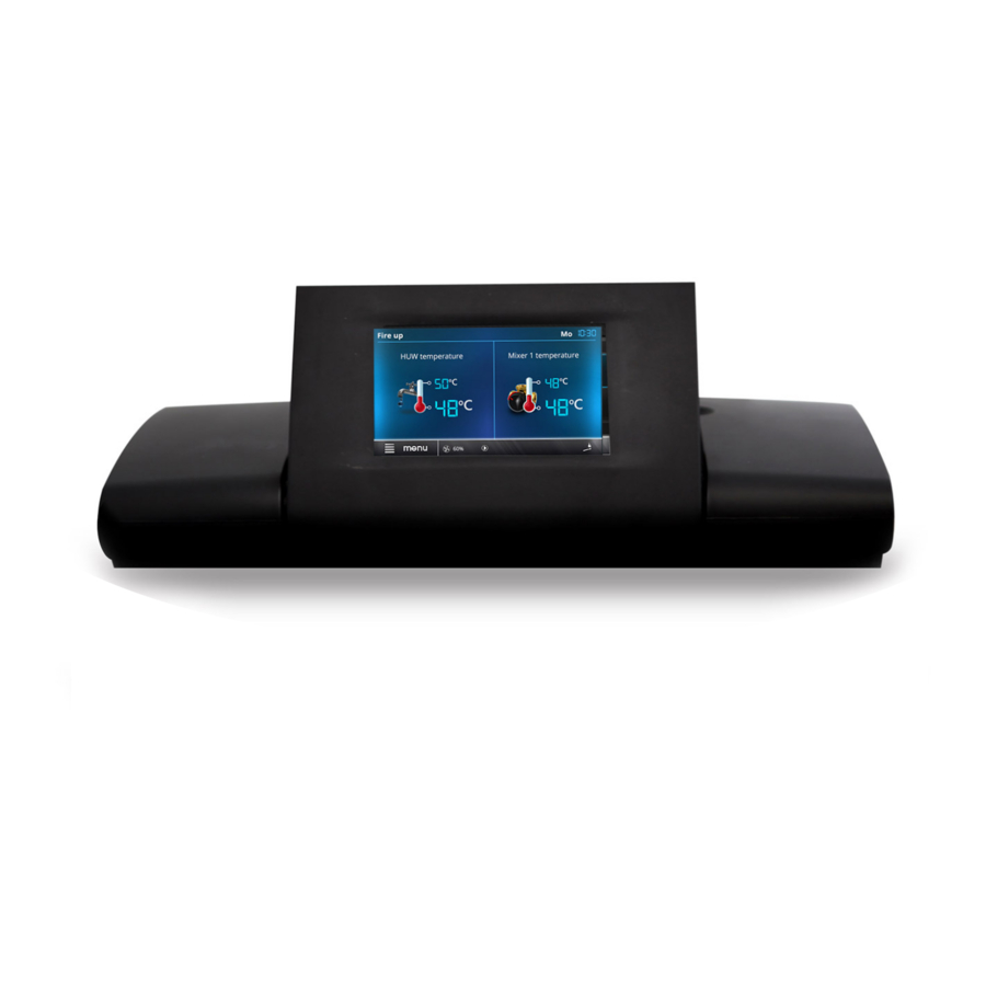
Page 9: The Regulator Support
The regulator support Description of the main window OPERATION Mon. Boiler temperature HUW temperature Legend: 1. Regulator operating modes: FIRE UP, functions having influence on preset OPERATION, SUPERVISION, BURNING boiler temperature. Following symbols signal OFF, CLEANING, STOP, respectively: 2. boiler preset temperature - holding down - preset boiler temperature decrease for a longer time - the value is edited, due to thermostat disconnection,... -
Page 10: Switching On And Off The Boiler
eSTER_x80, eSTER_x40 room thermostat / FIRE UP mode panel. The FIRE UP mode is for automatic firing up of furnace in boiler. Total time of firing up Switching On and Off the boiler process is dependand on controller’s settings and on boiler’s condition before firing up. Make sure fuel is present in the tank and Parameters influencing firing up process are tank hatch is closed. -
Page 11: Regulation Modes
Regulation modes Standard mode. In this mode the parameters H2 and H1 hysteresis do not have to be set. Can choose between two adjustment modes The Fuzzy Logic mode unlike the Standard responsible for stabilizing the boiler preset mode is not faulty in respect of failing to temperature Standard and Fuzzy Logic. -
Page 12: Burning Off Mode
mode is set using following parameters: from "pellet" to "grate". In the grate mode Boiler output in Supervision mode, Cycle fuel feeder is turned off. The combustion time and Fan output. process is regulated by the blow-in fan and The parameters in this mode must exhaust fan. -
Page 13: Huw Preset Temperature Settings
about it is displayed in the main window. By SUMMER mode act. temperature, so outdoor selecting: temp. above which the summer mode will be HUW settings → HUW pump mode the switched on SUMMER mode deact. user is able to: temperature, so outdoor temp. -
Page 14: Weather Control
Correction = (Preset room temperature - measured room temperature) room Settings for mixer with weather temp. temperature coefficient /10 sensor without room panel Example: Set parameter Mixer weather control to On. Select weather curve as per point 8.18. Preset temperature in the heated room (set Using parameter Heating curve shift, set room panel) -
Page 15: Night Decrease Settings Description
indicated by the symbol on the main screen. To activate time intervals, set the parameter Night time decrease for the given heating circuit parameter Reduction value temperature reduction, one for all time intervals. Night time decreases can be defined separately for every day of the week set Schedule. -
Page 16: Fuel Level Configuration
HUW setting → Night time decrease circ. Once selected and confirmed YES, fuel level pump is set to 100%. Note: Fuel may be replenished at any time Service settings → CH and HUW settings without a need to wait for complete empty Settings of time control of circular pump are fuel tank. -
Page 17: Information
function of the burner feeder should be panels has a built-in room thermostat. This enabled by the parameter Feeder filling. room panels shows useful information such as: fuel level, alarm indication etc. 8.24 Information Menu information enables view to measured 8.28 Cooperation with the Internet module temperatures and allows to check which of... -
Page 19: Installation And Service Settings
INSTALLATION AND SERVICE SETTINGS ecoMAX920P1-K TOUCH... -
Page 20: Hydraulic Schemes
Hydraulic schemes Scheme with 4 way steering valve controlling central heating circuit : 1 – boiler (control panel in the separated version), 2 – regulator, 3 – return temperature sensor, 4 – boiler temperature sensor, 5 – exhaust temperature sensor, 6 – servomotor of 4-way valve, 7 – mixer cycle pump, 8 – mixer cycle temperature sensor, 9 –... - Page 21 Scheme with two adjustable heating circuits and the HUW container : 1 – boiler, 2 – heat exchanger, 3 – regulator, 4 – boiler temperature sensor, 5 – exhaust temperature sensor, 6 – boiler pump, 8 – HUW pump, 9 - mixer valve actuator, 10 – mixer temperature sensor, 11 – mixer pump, 12 – standard room thermostat or ecoSTER TOUCH room panel, eSTER_x40 room thermostat, 13 –...
- Page 22 Scheme with heat buffer : 1 – boiler, 2 – control panel in the separated version, 3 –regulator, 4 – boiler temperature sensor, 5 – exhaust temperature sensor, 6 – boiler pump, 7 – heating buffer, 8 – HUW pump, 9 - mixer valve actuator, 10 –...
-
Page 23: Technical Data
During transport the controller cannot be Technical data exposed to vibrations bigger than typical for transport of boilers as well as direct pressure Power supply 230 V~, 50 Hz upon the clamp cover in order to protect the Current consumed by regulator 0,04 STB capillary, which is situated inside the Maximum rated current... -
Page 24: Mounting Of Module
Disassembly of control panel. To remove the control panel (1) from the Installation of control panel in boiler mounting plate. housing - insert flat elements (2) into indicated slots to release housing catches and remove the panel (1) 12.4 Mounting of module The regulator casing does not provide dust and water immunity. -
Page 25: Ip Protection Rate
regulator directly to hot gases and After deactivating the controller, there still can be a dangerous fire from the fireplace. voltage on the connections. Before In case of using the version with starting assembly works device before making obligatory disconnect montage and wiring it is strongly electrical power and make sure recommended to take out the STB... - Page 26 Cables secured from splitting should be connected to screw terminals of the (6) connector. Cables should be put through cable outlets in the casing (1) and secured from ripping or loosening by a holdfast (5 – break from casing). Cables insulation should stripped...
-
Page 27: Electric Scheme
12.7 Electric scheme... - Page 28 23 24 Scheme of electrical connections of the additional B module: M2, M3 – mixer 2 and 3 temp. sensor type CT4, RM2, RM3 – mixer 2 and 3 room thermostat, L N PE - electrical power 230V~, GR – grounding strip, PM2, PM3 –...
-
Page 29: Connection Of Temperature Sensors
The regulator cooperates only with a weather 12.8 Connection of temperature sensors temp. sensor of the CT6-P type. The sensor temperature sensors of the CT4 type. The should be installed on the coolest wall of the use of other types of temp. sensors is building. -
Page 30: Temperature Sensors Checking
CT6-P (weather) Temp. Min. Nom. Max. °C Ω Ω Ω 901,6 901,9 902,2 921,3 921,6 921,9 960,6 960,9 961,2 999,7 1000,0 1000,3 1096,9 1097,3 1097,7 1193,4 1194,0 1194,6 1384,2 1385,0 1385,8 1478,5 1479,4 1480,3 1572,0 1573,1 1574,2 CT2S-2 (exhaust) Temp. Min. -
Page 31: Reserve Boiler Connection
T1 (if the ecoSTER TOUCH or eSTER_x80 Controlling extension of the boiler room control panel is connected): is coshared with alarm extension. Service settings → Boiler settings → Deactivating additional boiler Thermostat select. control will cause that this In order for the room thermostat to control extension will be controlled by CH pump operation (without deactivating the module of controlling alarms. -
Page 32: Mixer Connection
Alarm signaling device must be connected set in mixer service settings proper time through a relay. On the matter that output is of valve opening (time should be written shared with reserve boiler control output, in on data plate of servomotor, e.g. 120s). order to activate the output for alarm ... -
Page 33: Connecting Temperature Limiter
During calibration, the servo is closed by the valve opening time. 12.18 Connecting temperature limiter order prevent boiler from overheating regulator malfunction, safety temperature limiter, or any other appropriate for the given boiler and heating system, should be fitted. When the STB is activated, the fan and fuel feeder motors are disabled. -
Page 34: Service Menu - Structure
Exhaust fan power 13 Service menu - structure Grate* Blowing power - supervision Service settings Blowing pause - supervision Burner settings Fan output - Grate mode Boiler settings Exhaust fan - grate CH and HUW settings ... - Page 35 CH on Floor on Pump only Thermostat select.* Minimum mixer temperature Maximum mixer temperature Proportional range Integration time constant Valve full opening time Pump off by thermostat Mixer input dead zone * Output H Heat exchanger cleaning ...
-
Page 36: Description Of Service Settings
14 Description of service settings 14.1 Burner Parameter Description Fire up Time to check whether the burner is already firing up. Only fan is operating. If the flame has sufficient brightness, it switches to the OERATION mode without the BURNING OFF Ignition test time mode. - Page 37 Blowing pause Break between airflows while burning off the fuel in burning off process. Blowing start Flame brightness with which airflow starts while burning off the fuel. Flame brightness with which airflow starts when burning off the fuel in burning off process Blowing stop Cleaning ...
-
Page 38: Boiler
14.2 Boiler Description Parameter Options to choose from: Off - deactivates room thermostat influence on boiler operation, Universal - activates room thermostat for boiler, ecoSTER T1 - option available after connecting room panel, boiler operation is dependant on room thermostat No1 in ecoSTER, ... -
Page 39: Buffer
breakdown of the controller water in the container can heat up to dangerous temperature. It is necessary to use additional protection in the form of thermostatic valves. Parameter determines how high the boiler temperature will be increased to load HUW container, buffer and mixer cycle. -
Page 40: Other Parameters
not cause exceeding preset temperature above value set in this parameter. - with parameter Mixer support = Floor ON is also limit temperature of mixer sensor when mixer pump is deactivated. For floor heating set the value below 45º…50ºC or other if producer of materials used for floor or CH installation designer state differently. -
Page 41: Alarms Descriptions
When alarm appears the boiler is activated. 15 Alarms descriptions The sensor is to be checked and replaced if necessary. The alarm can be deleted by Alarm numbers displayed on the wireless activating and deactivating power to the room thermostat. controller. -
Page 42: Unsuccessful Boiler Firing-Up Attempt
15.3 Unsuccessful boiler firing-up When temperature of the boiler decreases attempt below 5ºC pump will activated Alarm will appear after third failed attempt of enforcing circulation of boiler water. It will automatic furnace firing up. In case of alarm delay the process of freezing water, however all pumps are deactivated in order to not in case of very low temperatures or by lack cause... -
Page 43: Software Update
Default settings for given boilers / burners should be consulted with Company Plum Sp. z o. o. In order to load new parameters go to:... - Page 44 Service settings → [special password] and choose proper boiler/burner. Default settings can also be loaded by special software provided by Company Plum Sp. z o.
-
Page 45: Possible Faults Description
20 Possible faults description Symptoms Tips Check: There are no signs of operation of If line fuses are not blown, replace if necessary. device despite connection to the If the wire connecting panel with the executive module is plugged correctly and if network. - Page 48 Wspólna 19, Ignatki 16-001 Kleosin Poland plum@plum.pl www.pum.pl...
Need help?
Do you have a question about the ecoMAX920P1-K TOUCH and is the answer not in the manual?
Questions and answers